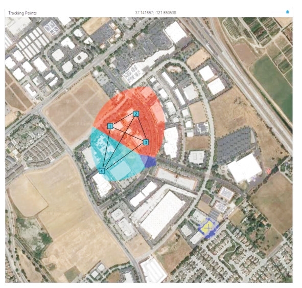
To view the coverage attained when adding and repositioning RSMs, click the
Create a Coverage Map icon. The AeroShield program displays the added lobes created when adding the fourth RSM as shown in
Figure: Four RSM Lobe Pattern.
Move the mouse pointer through the displayed RSM coverage area to view the triangular monitoring pattern for each set of RSMs. The lobe colors shown represent the lobe patterns created with maximum separation of 350 meters.