The linearity correction of the MA243x0A is compared to a thermal power sensor, which has very good inherent linearity over a power range of about –17 dBm to +4 dBm. For this reason, the MA243x0A is compared to the thermal sensor in two ranges, keeping the power levels to the thermal sensor in the range of –17 to +4 dBm, while the power to the MA243x0A varies from about –28 to about +14 dBm.
c. Repeat the measurement at synthesizer output level of +15, +10, +5, and 0 dBm.
8. Turn Off Synthesizer RF output
Note
The MA243x0A power measured at 0 dBm will be used in Step 9d, below.
9. Set up the test for the second 20 dB range as follows:
a. Remove the 10 dB attenuator from in between the reference sensor directly to the splitter.
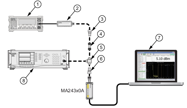
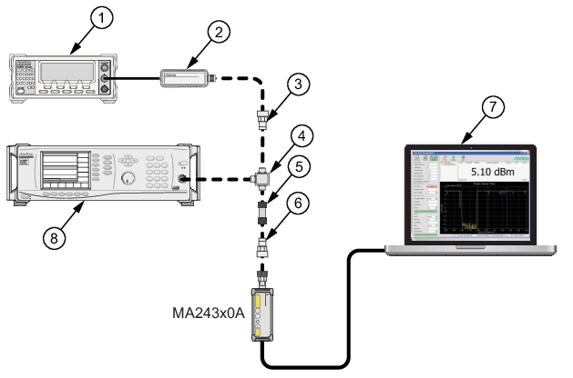
b. Remove the MA243x0A from the splitter and connect the 10 dB attenuator between the splitter and the power sensor (see Figure: Linearity Test Setup 2).
c. Turn On the synthesizer’s RF output.
d. Set the synthesizer output level to +10 dBm, then adjust its power level until MA243x0A reads as close as possible to the value recorded in column B row 5. Record the resulting power level in column B, row 6 of Table: Measurement Results (50 MHz).
e. Record the power indicated by the reference meter in column A of row 6.
f. Repeat the measurement at synthesizer output level of +5, 0, –5 and –10dBm.
.
Linearity Test Setup 2
Index
Description
1
Reference Power Meter
2
Reference Power Sensor
3
Adapter (if required)
4
Power Splitter
5
10 dB Attenuator
6
Adapter (if required)
7
PC with Anritsu PowerXpert Application
8
Synthesizer
Measurement Results (50 MHz)
Row #
Synth nominal level (dBm)
Atten in Ref Arm (dB)
Atten in Test Arm (dB)
A Ref Power (dBm)
B DUT Power (dBm)
C1
A6–A5 (dB)
C2
B6–B5 (dB)
D
A+C (dBm)
E
B5-D5 (dB)
F
(D-B)+E Diff (dB)
1
20
10
0
2
15
10
0
3
10
10
0
4
5
10
0
5
0
10
0
6
10
0
10
7
5
0
10
8
0
0
10
9
–5
0
10
10
–10
0
10
11
max
12
min
13
delta
10. Perform the calculations as follows:
a. Subtract the Reference Power Measurement of row 5, column A from the Reference Power Measurement of row 6, column A. Record this value in the column C1, rows 1 through 5.
Note
Column C1, rows 1 through 5 should all have the same value. The correction column rows 6 through 10 have values of 0.
b. Subtract the value in row 5 column B from that in row 6 column B. Copy the result into rows 6 through 10 of column C2.
c. For each row in column D, add the values of the same row of column A and columns C1 through C2 (a blank has value 0 dB).
d. Subtract the value of row 5 column D from that of row 5 column B. Record this values in column E rows 1 thorough 10.
e. For each row in column F compute the value by subtracting the value of column B from that in column D and then adding the value from column E.
f. Find the largest (most positive) value in the column F, rows 1 through 10, and record this value next to the word Max in row11.
g. Find the smallest value in column F, rows 1 through 10, and record this value next to the word Min in row 12.
h. Subtract the Min value from the Max value and record the result next to the word Delta in row 13. The Delta result should be less than 0.3 dB. If it is larger, contact Anritsu Customer Service.
11. Repeat the entire measurement and calculation with synthesizer frequency at 1 GHz, 5 to 50GHz in 5GHz step.