In this test the frequency response of the sensor is tested at one low power level against a reference sensor of known measurement uncertainty. The reference sensor should be calibrated by a reputable standards laboratory using instruments with low published measurement uncertainty values. To perform the comparison, both sensors are used to measure the output power of a synthesizer with a high quality power divider and an attenuator, such as the 41KC-6, on the output. The attenuator improves the source match of the synthesizer by lowering the mismatch ripples, thereby lowering the uncertainty in the comparison.
b. Connect the reference power sensor to the reference power meter using the appropriate cables.
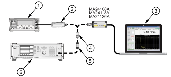
c. Connect the USB cable between the personal computer with the PowerXpert application installed and the MA24108A, MA24118A, or MA24126A power sensor under test.
d. Launch the PowerXpert application.
e. Turn the power on to all of the instruments and allow them to warm up for the amount of time specified in their respective manuals.
f. Reset or Preset all of the instruments.
g. Configure the reference meter and sensor to measure a CW signal.
h. Perform a sensor Zero and a 1 mW reference calibration on the reference sensor and meter per the manufacturer’s instructions.
i. Perform a low-level Zero of the MA24108A, MA24118A, or MA24126A power sensor by disconnecting it from the synthesizer, clicking the Zero button on the PowerXpert application, and waiting for the Zeroing message to close.
j. Connect the attenuator to the output of the synthesizer with the appropriate adapter (if required) to the output of the attenuator.
k. Set the synthesizer output power to +6 dBm and start frequency to 50 MHz.
MA24108A, MA24118A, or MA24126A Frequency Response Setup
5. Disconnect the reference sensor from the synthesizer output and connect the MA24108A, MA24118A, or MA24126A power sensor with the appropriate adapter (if required) and attenuator in-line. See Figure: MA24108A, MA24118A, or MA24126A Frequency Response Setup.
6. Apply the Cal factor to the MA24108A, MA24118A, or MA24126A by entering the frequency of the measurement in GHz.
12. For each frequency, compare the power difference to the maximum allowed difference specified in Table: MA24108, MA24118A, MA24126A Test Measurement Results. If the difference is higher than the maximum allowed difference, contact Anritsu customer service.
MA24108, MA24118A, MA24126A Test Measurement Results
Frequency (GHz)
A
Reference Power Measurement (dBm)
B
MA241xxA Measurement (dBm)
|A-B|
Absolute Value of Difference in Power Measurements (dB)
MA24108A and MA24118A Maximum Allowed Difference (dB)
a. Connect the reference power sensor to the power meter. Connect the USB sensor to the computer with supplied USB cable.
b. Connect the synthesizer and power divider to both sensors (No cable between synthesizer and attenuator).
c. Power up and reset all test instruments. Warm up for the period specified in their respective manuals.
d. Launch the PowerXpert application and configure both sensors to measure CW signal.
e. Turn off synthesizer RF output. Perform a sensor Zero and a 1mW Ref Cal on the reference sensor.
f. Perform Zeroing on the USB sensor by clicking Zero on the PowerXpert.
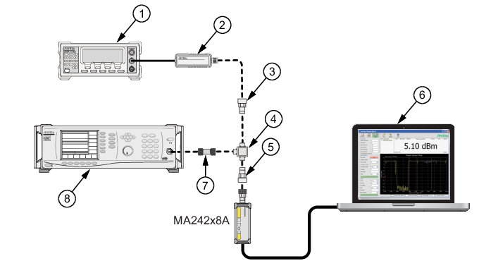
MA242x8A or MA243x0A Frequency Response Setup
Index
Description
1
Reference Power Meter
2
Reference Power Sensor
3
N(f) to K(m) Adapter
4
Power Divider
5
N(f) to K(m) Adapter
6
PC with Anritsu PowerXpert Application
7
6dB Attenuator Steps 3 and 9 or 3dB Attenuator Step 10
8
Synthesizer
2. Set Aperture Time to 20ms and Averages to 10 on PowerXpert.
3. Connect the 6dB fixed attenuator between Synthesizer and Power Divider. Set synthesizer output to +6dBm and 10MHz. Adjust output if necessary so the Ref sensor reads –6 ±0.2 dBm at 10MHz.
4. Apply Cal factor to both sensors by entering either the measured frequency or CF value.
6. Set the synthesizer frequency to the next value without changing the power. Repeat steps 4 through 5 to measure all listed frequencies.
7. Calculate the absolute value of the difference between the sensors and compare to the maximum allowed difference at each frequency.
8. Flip the power divider outputs and repeat the measurement If any difference is higher than the maximum allowed value. Average the measurements before and after the flip on both sensors and re-compute their difference. Contact Anritsu if the difference is still higher than the maximum allowed value.
9. Set synthesizer output to –6dBm and 10MHz. Adjust output if necessary so the Ref sensor reads –18 ±0.2 dBm at 10MHz. Repeat steps 4 through 8.
10. Change fixed attenuator from 6dB to 3dB. Set synthesizer output to +16dBm and 10MHz. Adjust output if necessary so the Ref sensor reads +7 ±0.2 dBm at 10MHz. Repeat steps 4 through 8.
MA24208 and MA24218A Test Measurement Results
Freq
GHz
A
Reference Power Measurement (dBm)
B
MA242x8A, MA243x0A Measurement (dBm)
|A–B| Absolute Value of Difference in Power Measurements (dB)