This section describes proper use and care of coaxial RF connectors.
Note
The components in Anritsu calibration kits are of the highest quality and accuracy. All components are NMI (National Metrology Institute) and NIST (National Institute of Standards and Technology) traceable. Mechanical shock can damage them. Handle with care.
Common Causes of Connector Failure
Following are common causes of connector‑related instrument failures and effects on measurement accuracy and repeatability.
• Connectors contaminated with material such as metal debris and dust particles will increase the risk of damaging connector. A dusty connector affects the measurement accuracy due to lack of repeatability.
• Worn or damaged threads can damage mating connectors.
• Over torquing connectors will introduce excessive stress to connector interface. Under torquing will increase repeatability uncertainty.
• Improper pin depth of the center conductor can permanently damage the mating connector.
• ESD—A connector is a perfect conductor for electrostatic discharge (ESD). Excessive charge accumulation will damage expensive and sensitive electronic devices residing in the instrument.
Coaxial Connector Care
Most coax connectors are assembled into a system and forgotten, but some, especially on test equipment are used almost continuously. The care and cleaning of these connectors is critical to maintain accurate and reliable performance. Good connector performance can be achieved with the following:
• Periodic visual inspection
• Routine cleaning
• Proper connection and disconnection techniques using a torque wrench
• Appropriate gauging techniques
Visual Inspection
Connectors contaminated with material such as metal debris and dust particles will increase the risk of damaging the connector. A dusty connector affects the measurement accuracy due to lack of repeatability. Careful visual inspection with a magnification aid and lighting should be performed at least once per day before connecting. A “good” connector may get damaged if it is mated with a “bad” one.
Any connector with the following defects should be repaired or discarded:
• Plating concerns that include bubbles, blisters, and deep scratches showing bare metal on the mating surfaces.
• Center conductors with bent, broken or damaged contacts.
Magnification
Use a device with a magnification range of 2X to 10X.
Magnification for Connector Inspection
Connector Type
Minimum Magnification for Inspection
Type N
2X
3.5 mm
7X
2.4 mm
K (2.92 mm)
V (1.85 mm)
W (1.0 mm)
10X
0.8 mm
Outer Conductor and Thread Inspection
When connector threads are clean and free from defects, coupling nuts should move freely. Inspect for defects such as:
• Dirt, dust, metal particles and oil
• Damaged threads (distorted, dented, or crushed)
• Dents or raised edges on the mating plane
Note
Connectors may lose some gloss over time due to normal usage. Light scratches, marks, and other cosmetic imperfections found on the mating plane surfaces are signs of normal wear and should not be considered cause for replacement.
Regular cleaning and proper connection techniques will minimize wear on the plating due to abrasion from debris.
Pin Depth
Pin depth dimensions are critical for the mechanical integrity, non-destructive mating and electrical performance of coaxial RF connectors. Before mating RF connectors, the pin depth of each device should be measured. This chapter provides instructions for properly measuring pin depth using the pin depth gauge provided in each applicable Anritsu calibration kit.
Mechanical gauging of coaxial connectors will detect and prevent the following problems:
Positive Pin Depth
• Positive pin depth or pin protrusion can result in buckling of the fingers of the female center conductor or damage to the internal structure of a device due to the axial forces generated.
Negative pin depth
• Excessive negative pin depth or pin recession can result in poor return loss, unreliable connections, and could even cause breakdown under peak power conditions.
A connector should be checked before it is used at a minimum of once per day when in use. If the connector is to be used on another item of equipment, the connector on the equipment to be tested should also be gauged.
Pin depth gauges should be checked for cleanliness before they are used at a minimum of once per month. The connector cleaning procedures in Connector Cleaning Instructions can be used to clean the pin depth gauges.
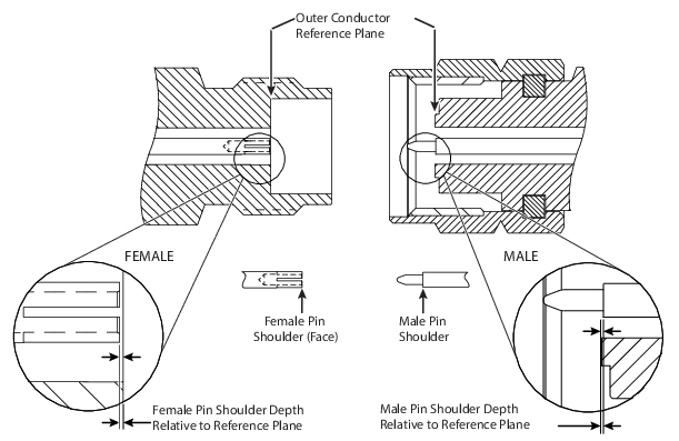
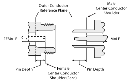
Pin Depth Defined
Pin depth is the distance between the outer conductor reference plane and the plane that intersects the shoulder of the male or female center conductor.
• For a female connector, it is the plane that intersects the shoulder (face) of the female center conductor.
• For a male connector, it is the plane that intersects the shoulder of the male center conductor.
Pin depth is not a performance specification but it provides an indication of the mechanical condition of the calibration kit components. By verifying whether the pin depth is within the expected range of limits, one can determine if the component is in good mechanical condition. Table: Pin Depth Limits (1 of 2) lists the range of the observable limits of each calibration kit component as shown on the pin depth gauge that is supplied with the calibration kit.
Note
Standards and government committees have created pin depth limits on the most common connectors to ensure the ability of mating with connectors of the same type. Components in the calibration kit might have a narrower acceptable range of pin depth limits due to electrical performance optimization.
Connectors on devices that mate with connectors of calibration kit components may not have the proper depth. They must be measured before mating to ensure suitability and to avoid connector damage to the components.
Anritsu Pin Depth Gauge accuracy specification is ±0.0002 in.
Pin Depth Limits (1 of 2)
Connector Type/Device Type
Observed Pin Depth Limits (Inches)
Male
Female
GPC-7
Terminations/Loads
–0.0002 to –0.0007 (GPC-7 has no gender)
Shorts
Not applicable due to design
Opens
–0.0005 to –0.0010
Type N
Note: For Type N connectors, the pin depth gauge (P/N 01-224) is zeroed on the +0.207 or –0.207 inch reference block depending on the gender of the N connector, so the gauge reading is always +0.000 to –0.002 inches for the 34 Series adapter, and +0.000 to –0.001 inches for Loads/Opens/Shorts.
34 Series Adapter (N to GPC-7)
Type N: –0.207 to –0.209 GPC-7: –0.0002 to –0.0007
Type N: +0.205 to +0.207 GPC-7: –0.0002 to –0.0007
1 Starting with kit serial number 1644002, part numbers 34AS50-2 and 34ASF50-2 (3.5 mm to GPC-7 Adapters) are not supplied with the 3650A/3650A-1 calibration kits.
Reading Pin Depth
When gauging pin depth, if the connector measures out of tolerance in the “+” region of the gauge, the center pin too long or is protruding. Mating under this condition can damage or break female pin contact fingers.
If the test device connector measures out of tolerance in the “–” region, the center pin is too short or is recessed. While this will not cause any damage, it will result in a poor connection and a consequent degradation in performance.
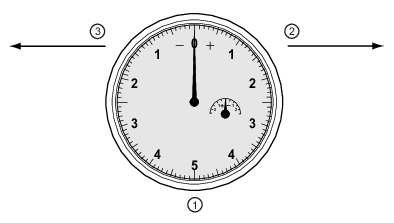
Pin Depth Gauge
1. Pin Depth Gauge with needle setting at zero. 2. Positive needle direction clockwise to right. Center pin is long or protruding. 3. Negative needle direction counter-clockwise to left. Center pin is short or recessed.