In some menus and screens, S11 is used to represent the S11 calibration parameter, S12 for S12, S21 for S21, and S22 for S22, and so on.
The auto calibration (AutoCal) process represents both a calibration kit and an algorithm that is used to speed up the calibration process with extremely high accuracy, minimizing the number of manual steps and test operator involvement.
Transfer Calibration
The 36585x-Series Precision AutoCal and the 36581KKF Standard AutoCal module calibrates the VNA by a process known as “transfer calibration.” There are a number of impedance and transmission states in the module designed to be extremely stable in time and these states are carefully “characterized”, generally by the Anritsu factory but also in a customer laboratory in certain cases.
When the same states are re-measured during a calibration, and the results compared to the characterization data, an accurate picture can be generated of the behaviors and error terms of the VNA and setup being calibrated.
Calibration Accuracy
A very high calibration accuracy is maintained through the use of certain principles:
• The use of many impedance and transmission states
• The creation of very stable states that are further enhanced with a constant-temperature thermal platform inside the module.
• The use of very reliable and repeatable solid-state switching constructed to provide a great variety of state impedances (for better calibration stability) and clean transmission paths.
• The use of a very careful characterization process that can generate excellent starting data.
The resulting accuracy, for some parameters, such as residual directivity, can exceed that obtained with typical mechanical calibration typically performed in a metrology laboratory. The variances, particularly on tracking, are related to pin depth variances on the test ports being calibrated and the practical difficulty in controlling those precisely.
The reflectometer portion of the calibration is based on the use of five reflection standards in an overdetermined algorithm. The standards were constructed to ensure that the reflection coefficients of at least three of them are far enough apart at every frequency to ensure an independent set of data. This was done through engineering of electrical lengths and added compensation. The transmissive part of the calibration is based on three transmission standards of varying insertion loss and return loss to add another level of overdetermined analysis. Finally, an assurance standard (yet another transmissive standard but with different parameters) is measured after the user calibration and the S-parameters compared against values stored at the factory. If these parameters all agree to within the measurement uncertainty, the message ‘Assurance Passed’ is generated and can give some confidence that the calibration was successful to within expected tolerances.
AutoCal Components
The AutoCal unit consists of the calibration module itself, a separate external power supply, a control cable that runs to the VNA, and the characterization data that is initially provided on a USB memory device. The AutoCal unit should be powered up and allowed to warm up prior to use (typically a few minutes, the blue Operate LED will illuminate when the unit is at temperature). Allow 90 minutes warm-up time for calibrations. The control cable should be connected to the serial port on the back of the VNA.
Connector Care
Since an AutoCal calibration is a very high performance calibration, connector care is of the utmost importance.
AutoCal Calibration Parameters and Types
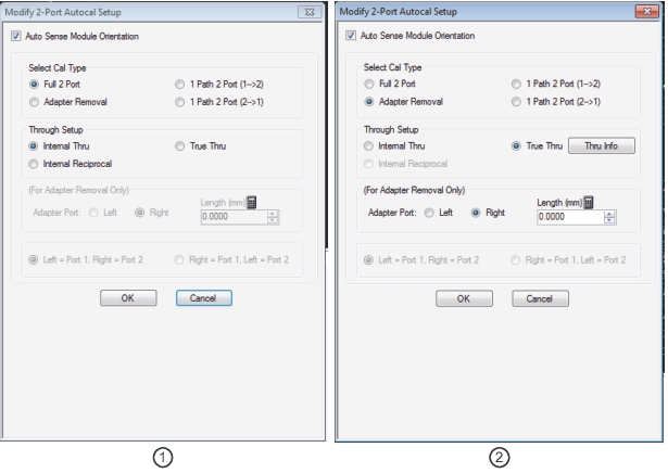
AutoCal for 2-port requires four general parameters be defined, as shown in the AutoCal dialog box:
MODIFY 2-PORT AUTOCAL SETUP Dialog Box
1. Settings (at left) for Full Two-Port Calibration with Internal Thru.
2. Settings (at right) for Adapter Removal and True Thru.
• whether to automatically or manually define the left/right test port assignments
• whether an adapter will be used with the AutoCal module.
Most standard calibration types are available with the AutoCal units. Frequency response calibrations are the only ones omitted since the AutoCal unit would provide no benefit in these cases since only a through or high reflect standard is needed for these calibrations. The AutoCal modules support:
• Full Two Port (also called Full 2-Port) calibration
• Full Port 1 (S11) reflection only calibration
• Full Port 2 (S22) reflection only calibration
• 1-Path 2-Port Forward (S11, S21) calibration
• 1-Path 2-Port Reverse (S22, S12) calibration
Adapter Removal
The DUT may require a different connector configuration than is on the current AutoCal unit (e.g., F-F DUT and the auto cal is M-F). AutoCal adapter removal is one way of handling this situation by performing two auto calibrations with an adapter connected to the AutoCal. The instrument will guide the user through the required connections.
Through Options
For each calibration type above, there are three through AutoCal calibration options:
• Internal Thru
The AutoCal module provides the internal through connections without the user having to move or reconnect the test cables. The benefit is speed of calibration balanced against potentially less accuracy and accommodates inexperienced operators, such as in an assembly line testing station.
• Internal Reciprocal
The Internal Reciprocal selection uses the same internal path as the Internal Thru selection, so there are the same advantages in terms of reduced connections required, but the path is treated as an unknown thru or reciprocal (see the Calibration and Measurement Guide for more information) and does not use the thru path characterization data. As such, it can provide improved accuracy in cases where the characterized thru does not perform as well (larger pin depth variations in the reference plane (cable-end) connectors, more environmental variation, etc.). The best-case-situation accuracy may not be quite as good relative to Internal Thru
• True Thru
All AutoCal modules can also be configured to allow True Thru where the user is prompted when and how to connect the test cables to complete the calibration. The benefit is a higher accuracy calibrations balanced against a longer calibration time and more operator involvement.
Test Port Left/Right Naming Assignments
The AutoCal module setup allows the user to specify the left/right identification of the test port cables as either:
• Auto Sense Module Orientation = ON
Where the module determines the left/right identification of the test port cables
• Auto Sense Module Orientation = OFF
Where the user defines either Left = Port 1 and Right = Port 2, or Left = Port 2 and Right = Port 1. This setting is useful where the VNA orientation is different for the operator.
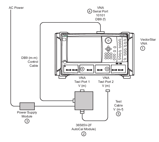
3. AutoCal Power Supply Module with extension able to local AC Mains power.
4. AutoCal DB9 (m-m) Control Cable connected between AutoCal Module and VNA rear panel Serial 10101 Port.
5. Test Cable V (m-f)
1. Prepare the VectorStar MS4645B or MS4647B VNA and power it up. The instrument has two V (m) test ports.
2. Connect the 366565V-2F Precision AutoCal Module V (f) connected directly to VNA Test Port 1 V (m).
3. The AutoCal module is then connected to its AC Power Supply Module and it to AC power
4. Connect the DB-9 (m-m) Serial Control Cable to the AutoCal module and the VNA rear panel Serial Port (10101).
5. The second AutoCal V (f) connector is connected to the V (m) end of the Test Cable. The test cable can be changed depending on measurement requirements. Cables on both VNA ports may be used, different types of cables may be used, or other configurations established. Then connect the V (f) end of the Test Cable to the VNA Test Port 2 V (m).
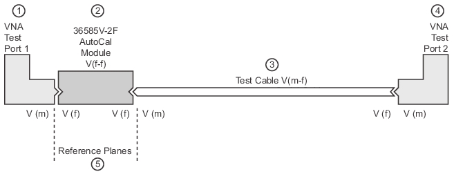
Schematic of AutoCal 36585V-2F Module Connections for Internal Thru
1. VNA Test Port 1 V (m)
2. 36585V-2F AutoCal Module
3. V (m-f) Test Cable
4. VNA Test Port 2 V (m)
5. Resultant reference planes
For optimal results, use the shortest cable lengths that do not require excessive bending when performing calibration or measurements. Results will be improved using the most practical phase- and amplitude-stable cables.
The power supply and control cables may be bundled for ease of routing or may be separated for convenience in some cases.
Using the AutoCal Module
The calibration procedure can be broken up into several simple steps:
1. Power up the VNA and connect the control cable to the AutoCal unit.
2. Install the characterization file if not already done. Copy the AutoCal Characterization File from the Characterization Memory Device (a USB memory device) onto the VectorStar hard disk drive.
Note
The AutoCal Characterization File (ACD file) is provided on a USB memory device and can be installed directly from that device. These files can also be copied from the USB memory device to the VectorStar hard drive and installed from there. The preferred method is to copy all ACD files onto the hard drive, and then install the file for the specific AutoCal being used.
3. Connect the AutoCal module to the VNA:
• AutoCal Module directly to one VNA Test Port
• A test cable between the AutoCal and VNA Test Port
• The Serial Control Cable between the AutoCal module the VectorStar back panel Serial 10101 port
4. Connect the AutoCal Module to its power supply and AC power. The green Power LED illuminates immediately. When the module is at operating temperature, the blue Operate LED will illuminate.
5. Setup the VNA instrument for the desired calibration:
• The required minimum settings are Frequency Start, Frequency Stop, and Number of Points.
• If required, optional settings for Segmented Sweep, IF Bandwidth, and/or Averaging are applied.
6. Select the AutoCal parameters of interest and connect the test port cables to the AutoCal unit. Make the required selections for Cal Type, Thru Select, Adapter Removal, and Auto Sense Module.
7. Perform the calibration by clicking Begin Cal to start the auto calibration.
8. A status dialog box with a progress bar appears after an AutoCal sequence has started. The status messages define has far the program has progressed and if any user actions are required.
9. At any time, the AutoCal sequence can be cancelled by clicking the dialog box Abort button.
10. If any manual steps are requested such as specifying a true-through, a dialog box will prompt for the action.
11. When the auto calibration is complete, a status message appears with a statement about assurance passing or failing. On the Calibration menu, the Cal Status field button shows ON.
Each procedure is described in greater detail in the following sections.