Adapter Removal—M-M or F-F Reference Plane with a M-F AutoCal
Adapter Removal Overview
Adapter removal for AutoCal modules primarily refers to the case of connector gender incompatibility when it is not desired to use test port converters such as when the user has a M-F AutoCal module and M-M reference planes are required. A separate menu item is provided for AutoCal adapter removal to speed up the process since fewer manual steps are needed. In this calibration sequence, one uses an adapter (that can mate the desired reference plane connectors) as part of the calibration.
Two possible scenarios are covered; both use a pair of calibration sequences to remove the effects of the adapter. In both of the cases below, it is assumed all connectors are from the same family. If not (e.g., one is using a special inter-series AutoCal unit), then this AutoCal-specific adapter removal technique may not be applied; see the standard adapter removal section.
This procedure performs an AutoCal procedure when an adapter is required to accommodate either the AutoCal unit or the DUT connector genders and a M-M reference plane is required.
Required Equipment
• VNA
MS4642B or MS4644B VNAs with K Test Port Connectors
• AutoCal Module
Precision AutoCal Module, 36585K-2MF, with K (f-m) connectors. Includes the necessary Power Supply Module with cords to AutoCal Module and to AC power
• Test Cable
A test port cable with K (m-f) connectors
• K (f-f) Adapter
A Matched K Adapter, 36583K with K (f-f) connectors.
Prerequisites
The following prerequisite procedures have already been accomplished:
• Required settings for Frequency Start, Frequency Stop, Number of Points, and CW Mode configured.
• Optional settings as required for Segmented Sweep, IF Bandwidth, Averaging, and Port Power configured.
Procedure
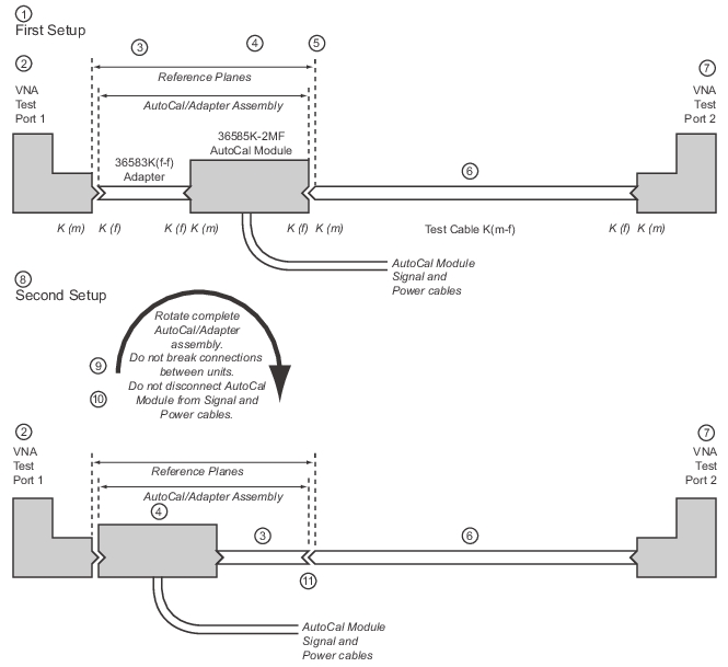
1. Make the necessary cable connections between the AutoCal Module, its Power Module, AC power, and the VectorStar back panel.
• When the blue Operate LED is illuminated, the module has warmed up and is ready for calibration operations.
2. Connect the 36583K (f-f) Adapter to the AutoCal K (m) connector.
• Consider the Adapter and AutoCal module as an “assembly” for the duration the AutoCal procedure.
Note
Once assembled, do not break the connection between the adapter and the AutoCal module, do not disconnect the assembly from the VNA Serial 10101 Port, and do not disconnect the assembly from AC power. If the connection between the adapter is broken before the AutoCal procedure is completed, the entire calibration is invalidated and must be repeated.
3. Connect the remaining 36583K (f) connector to the VectorStar Test Port 1 K (m) connector.
4. Connect the Test Cable K (f) connector to the VectorStar Test Port 2 K (m) connector.
5. Connect the Test Cable K (m) connector to the AutoCal Module K (f) connector.
4. 36585K-2MF AutoCal Module—For the duration of the calibration, the K (f-f) Adapter and the AutoCal Module must be connected as an assembly. Do not disassemble or disconnect from its Power and Signal cables.
5. Resultant calibration reference planes.
6. K (m-f) Test Cable
7. VNA Test Port 2
Part 2—AutoCal Adapter Removal Procedure
8. Second setup for the Adapter Removal procedure.
9. After the first calibration, rotate the complete assembly so that the AutoCal K (f) connector is connected to VNA Test Port 1. Do not disconnect the Adapter from the AutoCal module.
10. Do not disconnect the AutoCal Module from its Power or Signal cables.
11. Connect the 36583 K (f-f) adapter to the Test Cable K (m-f). The reference planes remain in place. The user is guided through the remaining steps of the procedure.
7. If the Cal Type, Thru Type, and Module Orientation display buttons do not show the correct values, select the Modify Cal Setup button.
• The Modify AutoCal Setup dialog box appears.
8. Make the following changes to the Modify AutoCal Setup dialog box settings:
a. Select the Auto Sense Module Orientation check box which allows the AutoCal module determine the left/right cable identification.
b. In the Select Cal Type area, select the Adapter Removal radio button. The For Adapter Removal Only area becomes available.
c. In the Through Setup area, select the Internal Thru radio button and Adapter Removal.
d. In the For Adapter Removal Only area, enter the estimate of electrical length (in mm) and select which AutoCal port the adapter is attached to.
e. Select OK to close the dialog box. The AUTOCAL SETUP menu reappears with new values for Cal Type, Thru Type, and Module Orientation.
Note
All existing system setups such as IF Bandwidth, Averaging, and Power Level will be applied during the calibration procedure.
9. When ready, click the Begin Cal button.
10. If the AutoCal module is connected incorrectly, the AutoCal Module Not Detected warning message appears. Correct connections as required and click Retry.
11. A status dialog box with a progress bar appears after an AutoCal sequence has started. The status messages define has far the program has progressed and if any user actions are required.
12. At any time, the AutoCal sequence can be cancelled by clicking the dialog box Abort button.
• When the first AutoCal process is complete, the user is prompted to reverse the Adapter/AutoCal assembly.
Note
Once assembled, do not break the connection between the adapter and the AutoCal module. If the connection between the adapter is broken before the AutoCal procedure is completed, the entire calibration is invalidated and must be repeated.
13. The instrument will prompt the user to reverse the module-adapter assembly.
15. Reverse the Adapter/AutoCal Module assembly so that the Adapter end is pointing towards Test Port 2.
16. On the AutoCal module, connect the free AutoCal Module K (f) connector to Test Port 1 K (m).
17. On the Adapter, connect the free Adapter K (f) connector to the Test Cable connected to Test Port 2.
18. When the auto calibration is complete, a status message appears with a statement about assurance passing or failing. Closing the dialog will return to the regular menu system. On the CALIBRATION menu, the Cal Status field button shows ON.