The following example presumes an MS4647B (70 GHz unit) with V connectors. A different connector can be selected in step 4 if a different model/configuration is being used. It is assumed that a M-F cable is connected to port 2 so that a M (port 1) and F (port 2) reference plane pair is available. In this example, a full 2-port SOLT calibration will be performed although a number of other options are discussed along the way. The implications of these options are discussed in the calibration overview section.
1. Setup the desired frequency range (Frequency menu), power (Power menu) and IFBW/averaging (Averaging menu). As a default, the IFBW will be 1 kHz and the averaging will be off which is adequate for many applications. The default power level will vary depending on instrument model and options but will often be adequate for all passive and many active device measurements.
2. Navigate to the TWO PORT CAL menu.
• MAIN | Calibration | CALIBRATION | Calibrate | CALIBRATE | Manual Cal | MANUAL CAL | 2-Port Cal | TWO PORT CAL
Note
If a previous calibration exists, the Thru Update button will be active. See Through (Thru) Update for more information.
3. Select Modify Cal Setup. The CAL SETUP menu appears. On this level, select a cal method of SOLT/SOLR and a line type of Coaxial.
a. Reference impedance defaults to 50 ohms and can be left there commonly. This value is used for referencing the standards reflection coefficients and for reference plane shift and Smith chart calculations. The latter two items can be handled later using a per-trace definition of reference impedance. The standards definition process is not affected by that later per-trace reference impedance change.
b. In the Load Type area, select broadband load. A sliding load can be used for better performance if one is available in the calibration kit. If low frequencies are included in the frequency range (< 4 GHz for V, < 2 GHz for K or GPC3.5), then a broadband load will be used in addition to the sliding load.
c. In the Through/Reciprocal/S2P Thru area, a zero-length (or mating) thru will be used. Set the Select Line field to Through, 0 mm for the length and 0 dB/mm loss. Zero can also be entered for the reference frequency. When 0 is entered for this value, no loss scaling is employed and the entered loss value is used for all frequencies. If a reciprocal network was being used instead of a through, use Reciprocal for the Select Line field and the length entered would serve as an estimate for root choice purposes.
If s2p thru was selected, the .s2p file describing the thru s-parameters would be loaded and used during the calibration. A 'characterize thru' option is also available using two previous reflection-only calibrations (with and without the thru element present) to calculate the .s2p file.
d. For Port 1, select a DUT connector of V(f). Note the dialog will then indicate that port connector is V (m).
e. For Port 2, select a DUT connector of V(f). The dialog will indicate a port connector of V(f).
f. For both ports, select a BB load of Load 1. This selection is for certain firmware/cal kit versions where modeled loads are available and the distinction between loads is important.
g. Select OK to close the dialog. Select Back at the bottom of the menu to return to the previous level and the TWO PORT CAL menu where two Reflective Devices buttons appear with six reflection standards on the two submenus.
Note
The menu calibration steps can be performed in any order. For this example, a top to bottom menu approach is assumed.
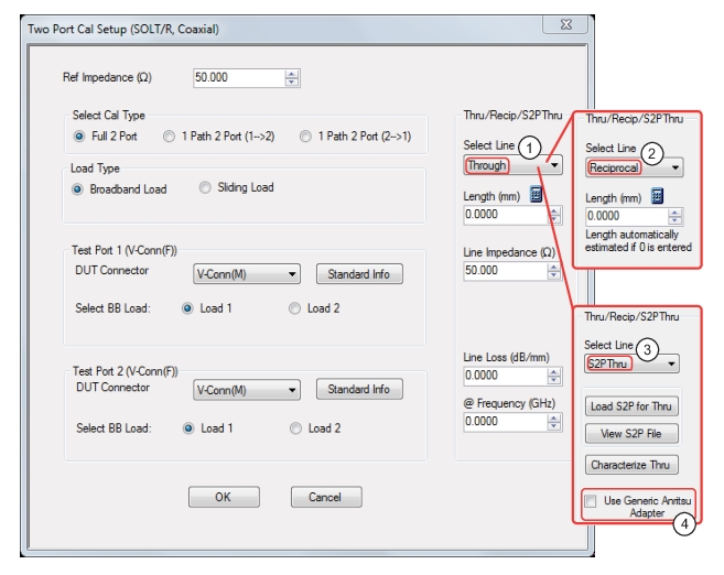
TWO PORT CAL SETUP (SOLT/R, COAXIAL) Dialog Box
1. Through selected allows user entries for length, line impedance, line loss and frequency.
2. Reciprocal selected allows user entry for length.
3. S2P Thru selected provides buttons for loading, viewing, and characterization (to generate S2P files).
4. Checking the Use Generic Anritsu Adapter checkbox will automatically load a default .s2p file for a generic Anritsu adapter. Note that selecting the checkbox disables the Load S2P for Thru and the Characterize Thru buttons.
5. Select Port 1 Reflective Devices and the REFL. DEVICES PORT 1 menu. On the menu, measure the three reflection standards of Open, Short, and Load.Connect each standard in turn, and THEN, click the corresponding button. When all are done, click the Back button to return to the TWO PORT CAL menu.
6. Then select Port 2 Reflective Devices and the REFL. DEVICES PORT 2 menu where next three reflection standards are listed. When all six are done (and six check marks appear), click Done to return to the previous level and the TWO PORT CAL menu.
7. After measuring all six reflection standards, connect the cable to Port 1 to complete the zero length through. Now click on the Thru/Recip button where a check mark should appear after the sweep pair. Note that the displayed graphs may change during this step as the instrument must measure all four S-parameters of the thru line.
8. An optional isolation step using the Isolation (Optional) button and the linked ISOLATION menu is available but is generally not recommended. If desired, terminate Port 1 and the end of the cable attached to Port 2 before clicking on the Isolation (Optional) button if needed.
9. Click on Done. The calibration is now completed and turned on where the Cal Status button on the CALIBRATION menu is set to ON.