The SSLT calibration differs from an SOLT calibration by the differing offset lengths between two shorts which are used to help define reflection behavior instead of an open and short. Because of this, the frequency range is limited since, at DC and at higher frequencies, these reflect standards will look the same. This method is most commonly used for waveguide problems where creating a stable, high reflection open standard is difficult, but there are certain coax and board-level or wafer-level situations where it is useful. The modeling constructs are about the same as for an SOLT calibration. From an error term perspective, the only difference is that the two shorts together now largely determine source match and reflection tracking behavior.
The electrical length difference between the shorts should be between 20 and 160 degrees over the frequency range of interest.
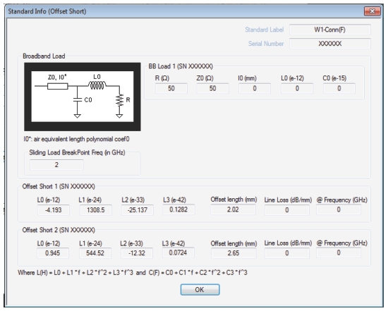
STANDARD INFO (OFFSET SHORT) Information Dialog Box
Typical parameters for Offset Short Calibrations
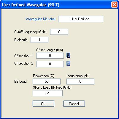
Variations for other line types (waveguide or microstrip) are similar to those for SOLT. For waveguide, the media and standards information are combined as shown in Figure: Waveguide Media and Standards Information. Defined, un-editable values would be present for Anritsu-defined cal kits.
Waveguide Media and Standards Information
Typical parameters for an Offset Short Calibration
A simplified short model is used for waveguide, with only an offset length and no inductance terms since usually those terms are small.
In SSLT, it is also possible to define the reflection standards with .s1p files as discussed in SOLT/SOLR Calibration for SOLT. Anritsu calibration kits for SSLT are generally for waveguide and do not include these .s1p files but the user can create them for any calibration kit based on measurement, electromagnetic modeling or other means. If based on measurement, it is recommended that a higher accuracy calibration form the basis of the characterization (e.g., LRL based on beadless airlines for coaxial situations).
As with SOLT, an .s2p-defined thru is also an option for SSLT. A file describing the 'thru' can be loaded to account for its loss and mismatch. Interpolation and extrapolation will be used if the file frequency list does not match the current calibration requirement.
As with SOLT, and even without .s1p definitions, the insertion loss of the opens and shorts can be defined. A loss variable is entered in dB/mm (which will be applied against the offset length) and the frequency (fref) at which that loss value applies. For other frequencies, the loss is scaled by sqrt(f/fref). If a 0 reference frequency is entered, the loss value is assumed to be constant with frequency. Sometimes, the loss of reflect standards is expressed as gigaohm/second at 1 GHz.
To convert those values to dB/mm, use this equation:
Equation 4‑1.
Where Z0 is the characteristic impedance (usually 50 ohms). Also, enter 1 GHz for the reference frequency, as the scaling is the same.