With an SSST calibration the three shorts together determine all of the reflectivities error terms (directivity, source match and reflection tracking). This calibration is more band-limited than the double offset short method. If short1 is defined as having the smallest offset length, and short3 to the longest offset length, then two variables can be defined:
Equation 5‑1.
The electrical length equivalents of A and B should generally be between 20 and 85 degrees over the frequency range of interest. This is not sufficient in itself since one will also require that A+B (which represents the difference between short1 and short3) also be constrained:
Equation 5‑2.
Since the only standards needed are shorts, this method is attractive for millimeter wave applications and for certain board-level and wafer-level calibrations where other types of standards are difficult to manufacture.
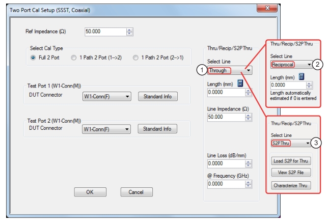
1. Through selected allows user entries for length, line impedance, line loss and frequency.
2. Reciprocal selected allows user entry for length.
3. S2P Thru selected provides buttons for loading, viewing, and characterization (to generate S2P files).
For one port calibrations, only one of the port definitions (unless reflection-only calibrations are being performed for both ports 1 and 2) will be present and the through line section will not be present. For a 1-path 2-port calibration, one of the port definition sections will not be present.
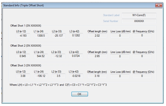
STANDARD INFO (TRIPLE OFFSET SHORT) Information Dialog Box
Typical parameters for SSST calibration—W1 (F) Connectors
USER DEFINED WAVEGUIDE (SSST) Information Dialog Box
Typical parameters for SSST calibration—Waveguide—User-Defined 1—Triple-Offset Short Calibrations
Note
Much like SOLT/SOLR, there is another version of SSST using a reciprocal in place of a thru called SSSR. Reciprocal measurements (using SOLR vs. SOLT as an example) are covered in more detail in Reciprocal Measurements.
In SSST, it is also possible to define the reflection standards with .s1p files as discussed in SOLT/SOLR Calibration for SOLT. The user can create these files for any calibration kit based on measurement, electromagnetic modeling or other means. If based on measurement, it is recommended that a higher accuracy calibration form the basis of the characterization (e.g., LRL based on beadless airlines for coaxial situations).
As with SOLT, an .s2p-defined thru is also an option for SSST. A file describing the 'thru' can be loaded to account for its loss and mismatch. Interpolation and extrapolation will be used if the file frequency list does not match the current calibration requirement.
As with SOLT, and even without .s1p definitions, the insertion loss of the opens and shorts can be defined. A loss variable is entered in dB/mm (which will be applied against the offset length) and the frequency (fref) at which that loss value applies. For other frequencies, the loss is scaled by sqrt(f/fref). If a 0 reference frequency is entered, the loss value is assumed to be constant with frequency. Sometimes, the loss of reflect standards is expressed as gigaohm/second at 1 GHz.
To convert those values to dB/mm, use this equation:
Equation 5‑3.
Where Z0 is the characteristic impedance (usually 50 ohms). Also, enter 1 GHz for the reference frequency, as the scaling is the same.