The MS464xB Series VNAs are equipped with an embedding/de-embedding system. De-embedding is generally used for removal of test fixture contributions, modeled networks, and other networks described by S-parameters (s2p files) from measurements. Similarly, the embedding function can be used to simulate matching circuits for optimizing amplifier designs or simply adding effects of a known structure to a measurement. Multiple networks can be embedded/de-embedded (E/DE) and changing the port and network orientations is handled easily. An extraction utility is part of this package that allows the easier computation of de-embedding files based on some additional calibration steps and measurements.
It is extremely valuable to be able to virtually remove or add networks to the measured data as described above. The process of adding network data to measured data is termed “embedding” while the process of removing network data is termed “de-embedding.”
Embedding Tasks
Common embedding tasks are to:
• View results as if a different launch structure was present
• View results as if a new matching circuit was being used
• View results as if an added cable length or transmission line length was needed
De-Embedding Tasks
Common de-embedding tasks are to:
• Remove the effects of a test fixture
• Remove the effects of a launch or launching transmission line
• Remove the effects of a test matching circuit that will later be physically removed
The MS464xB Series VNA embedding/de-embedding engine (E/DE) is a flexible tool for performing tasks of this type. A number of different circuit element primitives are available and full S2P files can also be loaded.
Note
Circuit parameters for embedding-de-embedding network elements are stored in S2P files that can be loaded into the VectorStar.
Embedding On/Off Control
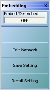
E/DE can be turned on and off with the Embed/De-embed toggle button at the top of the main MEASUREMENT menu as shown above (Figure: The MEASUREMENT Menu Set (1 of 2)) or with a duplicate toggle button at the top of the EMBEDDING control menu as shown below (Figure: EMBEDDING Menu).
EMBEDDING Menu
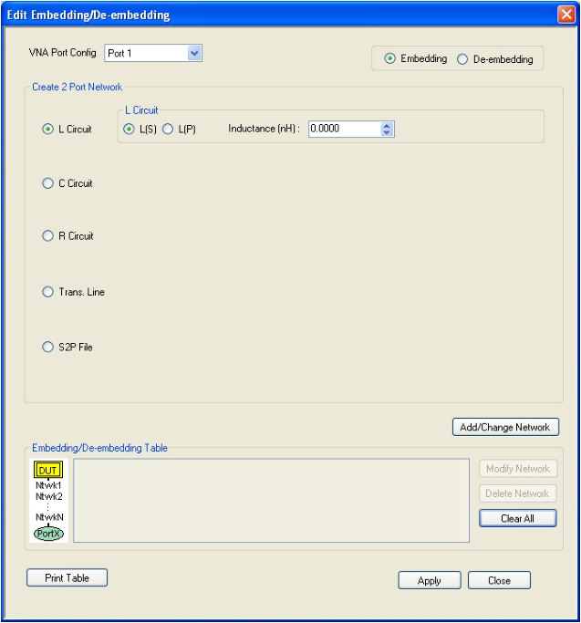
Clicking on Edit Network displays the main EDIT EMBEDDING/DE-EMBEDDING dialog box. An example with Embedding, L Circuit, and L(S) selected, but with no network information entered is shown in the figure below.
Embedding and de-embedding is set up for each port and the networks used on the two ports are entirely independent. Also, any number of networks can be cascaded at a given port and the first network entered is always nearest the DUT for embedding. Sequential de-embedded networks are used in the reverse order.
The key concepts for embedding and de-embedding are:
• Networks are setup on a per-port basis
• The networks used on the two ports are entirely independent
• Any number of networks can be cascaded at a given port
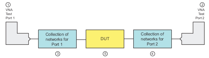
Global EDE Diagram Showing Independence of Port Networks
1. Test Port 1
2. Test Port 2
3. Collection of networks attached to Port 1.
4. Collection of networks attached to Port 2.
5. DUT attached to Port 1 networks (at left) and Port 2 networks (at right).
Types of E/DE Networks
There are five types of networks that can be entered:
• Inductive elements
• Capacitive elements
• Resistive elements
• Transmission lines
• .S2P-defined, file-based networks
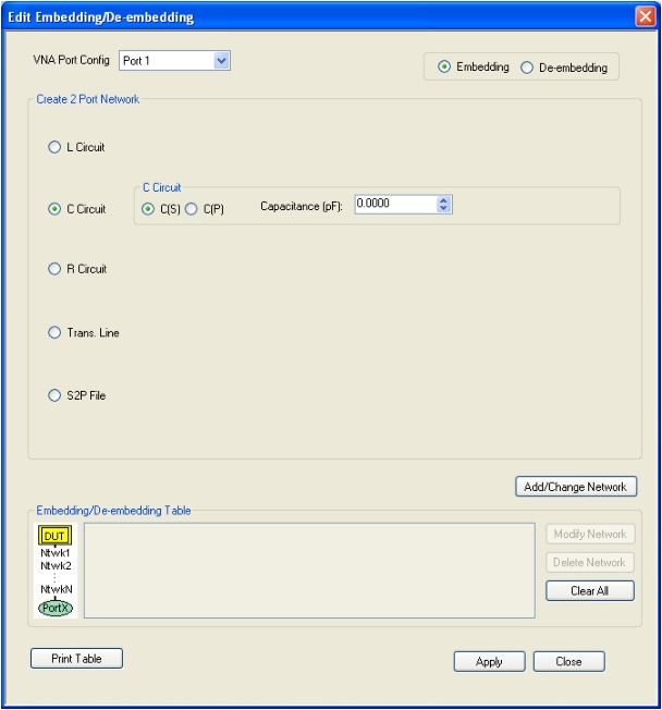
In the Edit Embedding/De-embedding dialog box in Figure: EDIT EMBEDDING/DE-EMBEDDING (2-Port DUT) Dialog Box—L Circuit above, the radio button for entering an LC network has been selected. An additional version of the dialog box is shown in the figure below where a C(S) network has been selected.
EDIT EMBEDDING/DE-EMBEDDING—C Circuit
Entry Mode for Resistive Elements
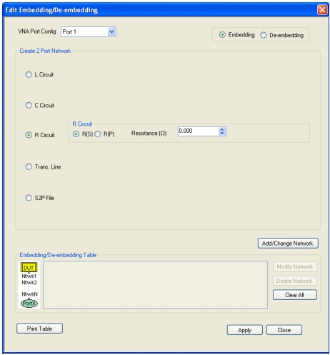
The entry mode for these resistive elements is shown in the E/DE dialog box below (Figure: EDIT EMBEDDING/DE-EMBEDDING Dialog Box—R Circuit Setup Selected). Both series (denoted by an (S)) and shunt (to ground) elements (denoted by a (P) for parallel) are allowed and selectable with the radio buttons. Since this element is symmetric, no orientation knowledge (with respect to DUT port and VNA port) is needed. The default units are:
• Inductance: nH
• Capacitance: pF
• Resistance: ohms
It should be emphasized that the shunt or (P) elements are always shunting to ground (not to the other port). If cross-port elements are desired, then the multiport version of the instrument should be used with an appropriate calibration.
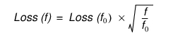
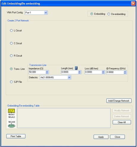
Transmission line entry is illustrated in the E/DE dialog box below (Figure: EDIT EMBEDDING/DE-EMBEDDING Dialog Box). As with transmission line entry in other parts of the system, loss can be entered along with a reference frequency. The loss at other frequencies will be computed using:
Equation 11‑1.
As elsewhere in the system, if a 0 (zero) frequency reference is entered, the loss value entered will be used as a constant at all frequencies.
EDIT EMBEDDING/DE-EMBEDDING Dialog Box
T-Line Selected—Transmission Line Element
Physical line length is normally entered here along with a dielectric constant but the calculator icon shown in above in Figure: EDIT EMBEDDING/DE-EMBEDDING Dialog Box can be used (which links to the AIR EQUIVALENT LENGTH CALCULATOR dialog box) if only a time delay is known. Again, since this element is symmetric, no orientation knowledge is needed.
Entry Mode for S2P Defined File-Based Networks
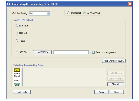
Finally, direct file entry of network S-parameters is shown in the E/DE below (Figure: EDIT EMBEDDING/DE-EMBEDDING Dialog Box). A standard S2P file format is assumed and the headers will be interpreted. The system will attempt to interpolate the provided data the best it can in the context of the current channel sweep range. If there is no overlap between the sweep range and the file frequency range, an error will be generated.
EDIT EMBEDDING/DE-EMBEDDING Dialog Box
S2P File-Based Element Entry
Note
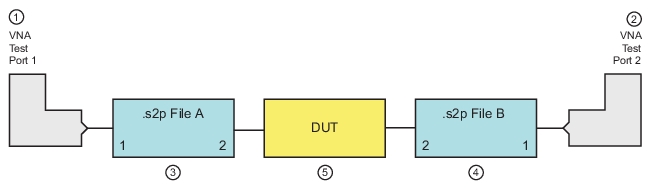
The network Port 2 is always assumed to be closer to the DUT regardless of which VNA port is involved. See Figure: Orientation of Loaded S2P Files. If “Swap port assignment” is checked, the relationship is reversed.
Orientation of Loaded S2P Files
1. Test Port 1
2. Test Port 2
3. .s2p File A—Port 1 to left, Port 2 to right.
4. .s2p File B—Port 2 to left, Port 1 to right.
5. DUT
Saving and Recalling Embedding Network Configuration
Once a set of networks (consisting of one or more individual networks) is defined, the E/DE configuration information can be saved to a file using the Save Setting button on the EMBEDDING menu (Figure: EMBEDDING Menu). Similarly, a stored E/DE setup can be recalled by using the Recall Setting button on the EMBEDDING menu.
The current E/DE setting is also saved as part of the master setup save (under the menu bar File menu) but multiple embedding and de-embedding circuits can be saved in these menus as well.