A simplified means of performing de-embedding (and embedding in some contexts) can be accomplished using reference plane control. The function of this control is to remove transmission line lengths from the data. By entering a time or distance, this length of line will be removed (negative lengths are allowed to effectively add length). Various dielectrics and the full dispersion choices (see calibration section of the Measurement Guide for more information) are available.
Reference Plane Menu
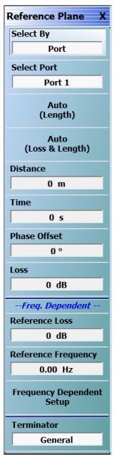
The REFERENCE PLANE control menu is shown in Figure: REFERENCE PLANE Control Menu. The ports are handled independently, as in E/DE, and the current port being affected is indicated by the toggle at the top of the menu.
Navigation:
MAIN | Measurement | MEASUREMENT | Reference Plane
REFERENCE PLANE Control Menu
Auto Button Functions
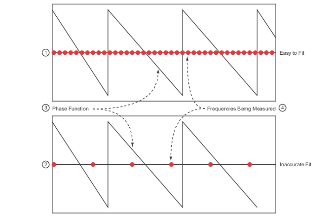
The Auto button performs a best fit operation to the current phase data to estimate the equivalent line length. It will attempt to generate a line length that, when removed, will make the phase flat. This routine will be less accurate if the DUT has very non-linear phase (a dispersion function not matching that selected) or if the DUT is electrically long relative to the current frequency step size. This latter problem, related to aliasing, occurs because not enough information is being collected relative to the true behavior of the DUT phase function (see Figure: Auto Reference Plane Function, Frequency Step Large Relative to Phase Period below). Increasing the frequency point density can help this problem.
Auto Reference Plane Function, Frequency Step Large Relative to Phase Period
1. Easier to Fit—Small frequency step size compared to phase function is easier to fit and yields higher accuracy.
2. Inaccurate Fit—Larger frequency step size compared to phase function is can produce inaccurate results.
3. Phase Function
4. Frequencies being measured.
Note: The auto reference plane function can produce inaccurate results if the frequency step (the distance between the red ovals in the figure above) is large relative to the phase function period.
Reference Plane Loss
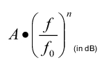
In addition to the frequency-dependent phase shift with length/time, the fixed phase shift and the fixed loss shift discussed so far, there is also a frequency-dependent loss term and an Auto Ref Plane function that applies to it. Unlike the linear-phase-with-frequency model assumed for length/time, the function form for loss/gain is:
Equation 11‑2.
Where:
• A is a nominal loss (or gain if negative) value in dB and f0 is the frequency at which that loss or gain value occurred. The functional form then describes the value at other frequencies.
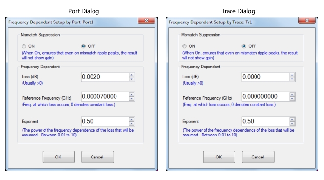
• The exponent n is user-selectable with a default value of 0.5 which tends to describe loss in coaxial lines and in coplanar waveguide rather well for many materials. The exponent may be closer to 1 for microstrip structures and other values for other geometries. The allowed range for the exponent is 0.01 to 10 but it is fairly rare to get outside the range of 0.25 to 2. The exponent, along with a mismatch suppression option for the auto ref plane process (to be discussed), are entered in a Frequency Dependent Setup configuration dialog (accessed from the Measurement | Reference Plane menu) as shown in Figure: Frequency Dependent Setup Dialogs (per-Port or per-Trace).
Frequency Dependent Setup Dialogs (per-Port or per-Trace)
The configuration dialog for some frequency-dependent loss reference plane items is shown above.
Per-trace and per port conventions apply for this frequency-dependent loss entry just as they do for the other reference plane parameters.
Reminder: Per-trace reference plane entries do not affect saved .sNp file results but Per-port entries do. In a transmission parameter, the reference plane correction will be the product of per-port reference plane adjustment functions from the involved ports (whether that is for regular S-parameters or user-defined parameters).
When the Auto Ref Plane Length/Loss is used, fits are done on both the phase (using the process described previously) and the magnitude (using the exponential functional form just mentioned) independently. Values for the fit parameters are entered in the appropriate menu fields and the adjustments applied to the trace data.
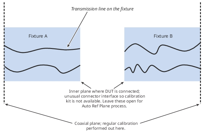
This frequency-dependent loss aspect of reference plane extension can be useful for very simplified de-embedding of fixtures or cabling. In one case, the fixture assembly is left with ‘opens’ at the DUT interface (a regular calibration was performed at the outer interface shown in Figure: Example Test Fixture). Using the reflection measurements at each port, the auto ref plane process can fit the loss (as well as length) and remove the effects of the fixture to some extent (other variations of this process use a thru connect between fixture halves and, in this case, a transmission parameter would be used). This is a simplified process in that match of the fixture itself is being neglected entirely and the loss of the fixture is assumed to follow the exponential dependence discussed. More accurate de-embedding methods (using a variety of network extraction tools) are discussed elsewhere in this guide that make use of (sometimes) additional standards or assumptions. The auto reference plane approach is, however, very easy to perform and may be adequate for more well-behaved fixtures and cabling structures.
Example Test Fixture
An example test fixture is sketched here showing how auto ref plane length/loss is used to perform very simplified de-embedding of the fixture response.
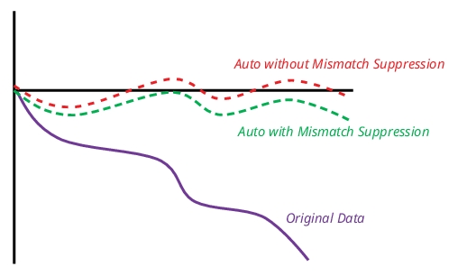
An additional option for the length/loss auto ref plane function is that of Mismatch Suppression. The concept is to limit that amount of loss correction so that no ripple peaks in the adjusted result exceed the initial (lowest loss) value of the parameter. If the DUT has very low loss at low frequency, not suppressing the effect of mismatch-induced ripple could result in an adjusted parameter value above 0 dB which may be objectionable in some applications. With Mismatch Suppression activated, the fitting process is modified so any ripple peaks will stay below the nominal initial value of the parameter in question. This concept is sketched in Figure: Auto Ref Plane Extension (Length/Loss) Effects.
Auto Ref Plane Extension (Length/Loss) Effects
Auto ref plane extension (length/loss) effects are shown here with and without mismatch suppression enabled for some example input data with considerable ripple.