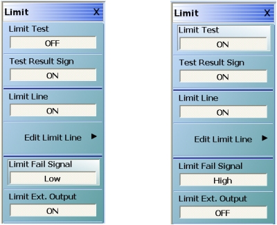
Limit lines are a powerful tool to help quickly compare a set of measured DUT data against specifications or expectations. All limit testing is per trace and, depending on firmware version, limit testing may only be available on rectilinear graph types. Upper and lower limits on any parameter may be set and these may be separated into many frequency bands. There is a limit of a total of 50 segments (upper and lower combined) per trace. The main limit line menu is shown in Figure: LIMIT Menu—Various Functions Toggled ON or OFF.
LIMIT Menu—Various Functions Toggled ON or OFF
The toggle buttons on the top level of this menu are straightforward:
Limit Test
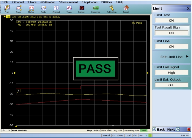
The Limit Test button enables comparison of the data to the limit lines existing (this is per trace). The results of the test (pass or fail) will appear in the upper right corner (see Figure: LIMIT Menu and Limit Pass Sign Example on Main Display) of the graph for that trace.
Test Result Sign
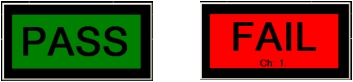
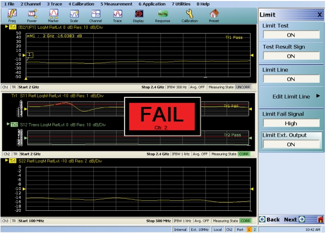
The Test Result Sign button enables a large graphic displaying the pass/fail result. This will be in the middle of the screen (see Figure: LIMIT Menu and Limit Pass Sign Example on Main Display below) and is visible from a large distance. The Limit Test must be on for this sign to appear. If any limit tests fail, the large fail sign will appear with a notation of which channel has failed.
Pass and Fail Signs Configured by the LIMIT Menu
Limit Line
Displays the current limit lines on the data graph. The limit lines will appear in red. Failing points are marked with a red dot.
Limit Fail Signal
Determines the state of the external limit status bit for a fail condition (see next item). High or Low (in a 3.3V logic sense).
Limit Ext. Output
The Limit External Output button enables a signal on pin 1 of the rear panel External I/O connector that will change state on limit failure. If any activated limit test fails, the bit will go to the fail state. This bit will be active only if Limit Test is ON. In the figure below, the small annunciator in the upper left appears if Limit Test is ON, the large center graphic appears if Test Result Sign is ON, and the red limit lines appear if Limit Line is ON. If a test on a channel fails, the large center graphic includes a notation of which channel has failed.
LIMIT Menu and Limit Pass Sign Example on Main Display
A more complex, multi-channel example showing some of these concepts is shown in Figure: LIMIT Menu and Limit Fail Sign Example on Main Display. Note the dependence of the Test Result Sign on the limit testing going on in multiple channels. Only Trace 1 on Channel 2 has failed, but the overall result will be reported as a failure.
LIMIT Menu and Limit Fail Sign Example on Main Display
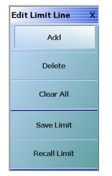
Editing Limit Lines
The editing of the limit lines is controlled on the one submenu and that is shown in Figure: EDIT LIMIT LINE Menu. When entering this menu, the limit line table will appear at the bottom of the screen (not unlike the multiple source and segmented sweep tables). Initially, the table will often be empty. If a limit line set was created on another trace, those values may appear here but they may be cleared or edited. The limit line tables may be saved and recalled separately using this menu (much like segmented sweep tables) or they may be saved and recalled as part of the global setup (use commands under the File menu to do this).
Edit Limit Line Menu
EDIT LIMIT LINE Menu
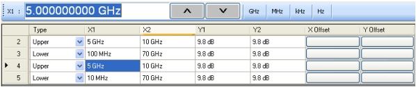
An example limit line table is shown in Figure: Limit Line Table using two upper limit segments and two lower limit segments. For each segment, a number of things need to be entered: Upper or lower: Use the pull-down to indicate if it is an upper limit or lower limit. Another option on the pull-down is “off” to enable suspension that segment.
X1 and X2
The constraints of the segment in the X-direction. Usually this variable will be frequency (segmented or linear frequency sweeps) but it could be time (time domain) or power (power sweep). If two segments cover the same frequency range (or portions thereof), the first segment will have precedence.
Y1 and Y2
The constraints of the segment in the Y-direction. These will have units of the graph type for the active trace (dB in the examples here).
Limit Line Table
The X offset and Y offset values allow one to shift both indices in a row by a constant amount. This can be useful in copying multiple rows and, for example, incrementing by a fixed frequency offset.