This chapter provides general measurement setup fundamental concepts, requirements, and options for different types of measurements. Specifically, this chapter describes channels, traces, limit lines, external analog input/output, averaging, and smoothing and organizes their configuration in the same hierarchy. Channel is the highest level configuration with up to 16 channels possible, each with a different frequency range, power level, IF bandwidth, and RF calibration. On a per-channel basis, traces are lower level concepts that represent a data group with up to 16 traces per channel. Limit lines are described with setup tasks and test functionality. External analog input/output is described with setup issues, range, functions, resolution, and accuracy. A description of averaging and smoothing with their available functions and the effects on measurements conclude the chapter.
Channels and Traces Introduction
Two of the central concepts in the MS464xB Series VNA family that will enable the maximum functionality of the system are channels and traces.
Channel Concept
At a high level, the channel defines the sweep configuration and the calibrations for a measurement. Sixteen channels are possible and each can have a different frequency range, different power levels, different IF bandwidths and different RF calibrations (among other things). In a sense, 16 distinct VNAs within one instrument are possible with each one executing sequentially.
Trace Concept
The trace is a lower level concept that represents a data group. Sixteen traces are allowed per-channel and each can represent a different response parameter, can be on a different graph type, and have certain different levels of post-processing applied to it.
The objective of this section is to explore how the channels and traces can be set up, what possibilities are available, and what configurations are commonly used. Many of the functions of the VNA can be separated into per-channel and per-trace groups; the delineation of these functional groups is also an important part of this section.
Channels and Traces General Concepts
The hierarchy of setups is illustrated in Figure: Setup Information Hierarchy (1 of 2). At the highest tier is per-system; these are variables that apply to all measurements on a given physical instrument. There are very few of these variables and they include:
• Step attenuator settings
• Bias tee on/off
• Certain portions of the hold system and certain triggering functionality
• AutoCal characterization files and cal kit files (are accessible from any channel)
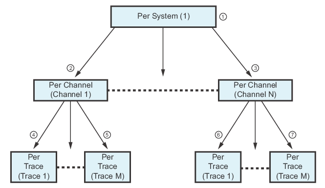
These variables are often per-system to prevent a setup scenario that could significantly shorten the life span of the hardware. In the case of hold and triggering, it also allows an entire measurement suite to be somewhat more easily controlled externally. Others fall more in the category of utilities that are somewhat per-system in nature. The hierarchy of system, channel, and trace setup information is shown below. Generally, N (the channel count) may be up to 16 (except when more than 25,000 points in a sweep are needed) and M (the trace count) may always be up to 16.
Setup Information Hierarchy (1 of 2)
Setup Hierarchy—System, then Channels, and then Traces
1. Per System Settings—These settings affect the entire instrument such as the maximum number of measurement points as either 25,000 or 100,000.
2. Per Channel Settings—If in 25,000 point mode, from 1 (one) to 16 channels can be configured. If in 100,000 point mode, only one channel is available.
3. Per Trace Settings—Each configured channel can have from 1 to 16 traces. Each trace can be configured as a separate measurements, with separate markers, and a different display method. Each trace can have up to 12 total measurement markers and one (1) reference marker.
Per-Channel Variables
The second tier is that of the channel. As mentioned in the overview, the channel can almost be thought of as a separate virtual VNA. Although this term has been used differently in the past with other Anritsu VNAs, in the MS464xB Series VNA Series family, it includes a separate frequency list, separate calibrations and separate sweep control.
Per-Trace Variables
The third tier is that of the trace. As discussed above, this can be thought of as a data element (for example, S21 data for a given channel-based sweep setup). The per-trace flexibility mainly comes under the heading of post-processing and display.
Note
For historical reference, the 37xxxX family of Anritsu VNAs was limited to 1 channel and 4 traces. Although it may be somewhat confusing, in those instruments, what we now call traces were, then, called channels. This discrepancy was difficult to avoid when transferring to modern usage of the terminology.