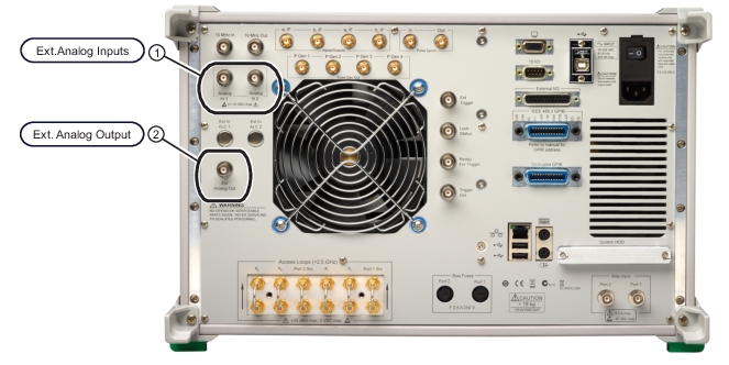
The VectorStar MS464xB-Series VNA has two external analog inputs (Figure: Rear Panel External Analog I/O Ports) where the voltages may be plotted on the same graph types as S-parameters and un-ratioed parameters. Examples include the use of external power detectors or external current probes (to measure amplifier current draw as a function of frequency or power for example). Like everything else on this menu, it is a PER-TRACE selection.
Rear Panel External Analog I/O Ports
MS4647B VNA Rear Panel Example.
1. External Analog Input Ports (at upper left)
2. External Analog Output Port (at upper center)
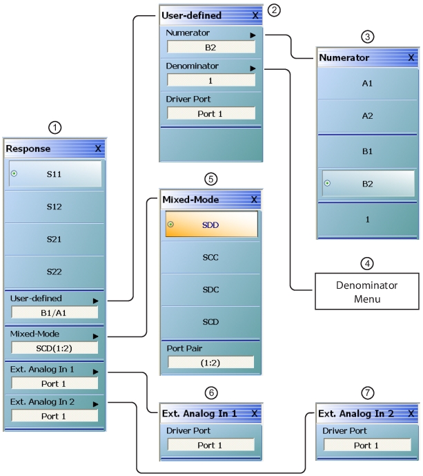
Response Menu
These are selectable on the response menu as shown in Figure: RESPONSE Menu and Submenus below. The submenu allows a choice of which port is driving during that particular analog in measurement. This port selection may be important particularly with the use of external power detectors.
RESPONSE Menu and Submenus
1. RESPONSE menu
2. USER-DEFINED menu
3. NUMERATOR menu
4. DENOMINATOR menu (not shown, the same as NUMERATOR menu)
5. MIXED-MODE menu
6. EXT. (EXTERNAL) ANALOG IN 1 menu
7. EXT. ANALOG IN 2 menu
Rear Panel External Analog Input Ports
These rear panel ports route through a multiplexer to an additional A/D converter. Internal calibration standards are used to correct for offset and channel gain slope, so the accuracies are on the order of 2 mV + 1% for absolute voltages under 5V and 2% for high voltages. The calibration is performed at power on and can be triggered from the diagnostics menus if necessary (see operation manual for details). This calibration is based on a pair of voltage references built into the instrument, so a linear error model of the low frequency analog in path can be generated.
The maximum range for the inputs is ±10V and the nominal input impedance is 60 kΩ. While the input is primarily intended for DC or very-low-frequency measurements, it has a bandwidth of approximately 1 kHz.
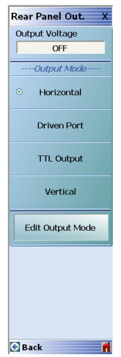
External Analog Out Port
There is also one external analog output port on the MS464xB-Series VNA and it is primarily used for sweep synchronization and certain triggering tasks of external instruments or DUTs. The control menu is located under MAIN MENU | SYSTEM | REAR PANEL OUT. and is shown in Figure: REAR PANEL OUT. (REAR PANEL OUTPUT) Menu.
REAR PANEL OUT. (REAR PANEL OUTPUT) Menu
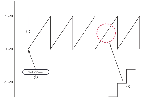
The top button is a toggle on/off while the next three buttons select the output mode. Horizontal is a sawtooth wave synchronized with the sweep (resetting to the start voltage at the first point of the sweep). This output really is a sequence of steps (see Figure: Horizontal Output Waveform) whose width is determined by the per point measurement time.
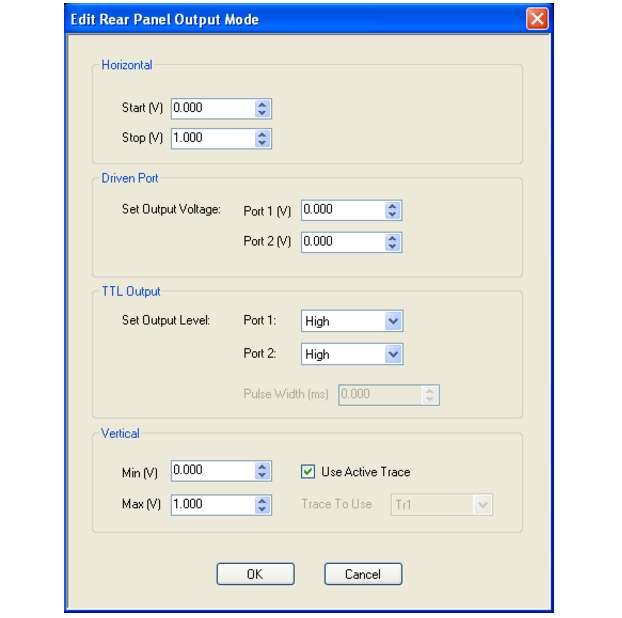
The horizontal output mode waveform for the settings of Figure: EDIT REAR PANEL OUTPUT MODE Dialog Box is shown below. The waveform is actually composed of small steps whose width represents the per-point sweep time.
Horizontal Output Waveform
1. Horizontal sweep waveform.
2. Start of horizontal sweep.
3. Close-up view of waveform showing small steps representing the per-point sweep time.
Driven port produces a static voltage level that is different when Port 1 is driving versus when Port 2 is driving. The TTL output is either a static logic value or a pulse (high-going or low-going) at the start of a sweep in a given direction. The details of the output are controlled in a dialog launched by the Edit Output Mode button (see Figure: EDIT REAR PANEL OUTPUT MODE Dialog Box).
For the first two modes, the allowed voltage range is +/- 10V with an accuracy of about 20 mV + 2%. For TTL output, the selections are high, low, high pulse, and low pulse. The pulse will occur at the start of the sweep for the given driving port and the pulse width is adjustable. Although 0 pulse width may be entered, the actual minimum pulse width is about 0.5 μs. The maximum pulse width can exceed 10 s but note that if the pulse width becomes large relative to the time to complete the sweep, the instrument will wait for the pulse cycle to complete to avoid pulse collisions on subsequent sweeps.
EDIT REAR PANEL OUTPUT MODE Dialog Box
The vertical selection will generate an analog output proportional to the plotted value on the active or selected trace data. This can be useful for generating feedback for a position controller or for analog data recording techniques. As shown in the setup dialog, a maximum (corresponding to the top line on a rectilinear graph type) and a minimum (corresponding to the bottom line on a rectilinear graph type) voltage should be entered within the usual +10V to –10V range for this output connector. Some points to observe:
• The voltage will only update when the channel in question is sweeping (the channel on which the rear panel output: vertical was selected). Any channel can have this control active and the rear panel output voltage will update according to the active/selected trace value when that channel is sweeping.
• For all single rectilinear graph types (log mag, linear mag, real, imaginary, phase, group delay, power out, power in, impedance…), the maximum and minimum voltages will correspond to the top line and bottom line of the graph, respectively. If the plotted parameter value goes outside of the graph (with its present scaling), the voltage output will clip at the maximum or minimum value.
• For dual rectilinear graph types (log mag + phase, real + imaginary…), the top graph will control the output.
• For Smith Charts, the maximum voltage corresponds to the outer rim of the chart and the minimum voltage corresponds to the center (and always in the sense of radius of the point being plotted… the parameter reflection/transmission magnitude in linear terms). For log and linear polar graph types, the maximum voltage corresponds to the outer rim of the graph (the reference value on the scale menu) and the minimum voltage corresponds to the outer rim value less five of the resolution values (also on the scale menu). Again, this output will be in the sense of magnitude of the parameter.
Example: Linear polar with reference value of 5U and a resolution of 0.2U/div.
The maximum voltage will correspond to a magnitude of 5U and the minimum voltage will correspond to a magnitude of 4U (5-5*0.2).
• The output will correspond to the plotted value, which means it is after all post-processing. If the display on the active/selected channel is static (e.g., memory-only display has been selected), then the output voltage will be static.
• The functionality will not be useful in modes where the trace updates all at one time (e.g., time domain—Option 2; pulse modes—Option 42; true mode stimulus—Option 43).
Example: Suppose one has used the vertical out feature on the 37XXX VNA in the past and wished to mimic that behavior in the MS464XX VNA for a phase graph type.
The 37XXX analog out vertical feature was limited to 1V/div and always worked on the active 'channel' (which is equivalent to the trace for the MS464XX). Thus the voltage range was always –4V to +4V for rectilinear graphs since the 37XXX rectilinear graphs all had 8 divisions. To perform the same setup on a MS464XX, either make the desired trace active or select it from the dialog, select the desired graph type (phase in this case), and enter a voltage range of –4V to +4V on the rear panel out setup dialog.