The receiver cal offset is a file that can be used to modify the receiver calibration used in noise figure measurements when it is known that there are some power discrepancies within that receiver calibration.
Examples of this situation include:
• The only power calibration that could be performed was at a higher level than that where the receiver calibration was performed and one wishes to correct for the frequency response of a pad/attenuator (or other means of power reduction) used for the receiver cal.
• The source used for the receiver calibration had some harmonic content that could cause inaccurate power readings relative to the receiver calibration readings. Knowledge of these harmonic levels can be used for a correction.
• There are other known inaccuracies with the power calibration (due to fixturing, bandwidth, etc.) that one wishes to correct for.
A common scenario for using this function is in mmWave noise figure measurements when high dynamic range power sensors are not available (bullet one above) and a factory receiver calibration of the mmWave module is available to help. This case will be covered in detail at the end of the section.
The file format is a standard text file (.txt) and is the result of a Save Data operation with a single trace enabled in Log Mag display format.
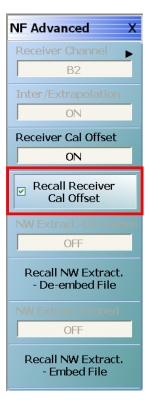
Advanced Noise Figure Menu: Receiver Cal Offset
The response parameter is b2/1 in this case but can be anything appropriate (usually will be b2/1 or S21) to describe the response. The data in this file should represent the power error incurred when doing the receiver calibration: a value > 0 dB means the actual power was higher than the system detected during the receiver cal and a value < 0 dB means the actual power was lower than the system detected.
A segment of an example text file is shown below. This is the file format used for the receiver cal offset correction. The response parameter can be anything but will most commonly be S21 or b2/1.
MS4647B
!10/23/2013.12:32:31.PM
!CHANNEL.1
!TR.MEASUREMENT
!RF.CORRECTION.OFF
!AVERAGING.OFF
!IF.BANDWIDTH: 10HZ
!NUMBER.OF.TRACES: 1
!TRACE: TRACE.1
!PARAMETER: B2/1
!PORT: PORT1
!GRAPH: LOGMAG
!SMOOTHING: OFF
!TIMEDOMAIN: OFF
!SWEEPTYPE: FREQ.SWEEP(Linear)
PNT FREQ1.GHZ LOGMAG1
1 80.001000000 -8.735106E+000
2 80.150995000 -6.820481E+000
3 80.300990000 -6.195999E+000
4 80.450985000 -6.687141E+000
5 80.600980000 -6.155944E+000
6 80.750975000 -6.188873E+000
7 80.900970000 -6.445963E+000
8 81.050965000 -6.779163E+000
9 81.200960000 -6.733072E+000
10 81.350955000 -6.922758E+000
11 81.500950000 -7.044048E+000
12 81.650945000 -7.252111E+000
13 81.800940000 -6.779829E+000
14 81.950935000 -7.133829E+000
15 82.100930000 -7.282691E+000
16 82.250925000 -7.258348E+000
17 82.400920000 -7.333891E+000
18 82.550915000 -7.438091E+000
19 82.700910000 -7.777820E+000
20 82.850905000 -7.632741E+000
21 83.000900000 -7.665494E+000
Examples
1. An uncompensated adapter with 1 dB of loss was used for the receiver calibration but was not present during the power calibration. The power seen by the receiver was 1 dB lower than what the power calibration is reporting.
In this case the values in the file will all be around −1 dB. This can be measured with a simple S-parameter measurement of the adapter (using adapter removal or reciprocal techniques as necessary if the connections required are not mateable).
2. Another example is in mmWave systems where power sensors that operate at the desired levels for the receiver calibration (which may be −50 dBm or lower) are rare.
If measurements are performed with the 3744A-Rx direct receiver module, there is a correction path available. This module is usually supplied with a factory receiver calibration file that one can use to back-propagate accuracy to the source power so that when one performs the 'real' receiver calibration for noise figure (with a pre-amplifier/filter assembly attached), the correct receiver calibration values can be obtained indirectly.
Creating the Receiver Cal Offset File
1. Connect the desired source reference plane to the 3744A-Rx module at the target power level (−60 dBm for this example).
2. Load the provided factory receiver calibration file.
3. Set the frequency range to the one desired for the noise figure measurement (with an adequate number of points) and set the display for single trace, b2/1|P1, log mag.
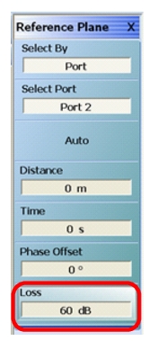
4. Set the reference plane magnitude to correct for the intended power level (60 dBm in this case) as shown in Figure: REFERENCE PLANE Menu with Adjustment. The resulting data then represents an error from the ideal power level and helps to describe the actual source power in a nominal bandwidth of interest.
5. Save the resulting data as a text file. This step creates the receiver cal offset file for the measurement.
6. Connect the rest of the assembly for the noise figure measurement (pre-amplifiers and filters normally) between the 3744A-Rx module and the source reference plane, leaving the power setting the same.
7. Perform the receiver calibration on this setup and save the results as a text file.
8. Load the receiver calibration file from Step 5 and the receiver cal offset file from Step 7 when performing the noise figure calibration and measurement.
9. Load the DUT S-parameters and perform the noise calibration.
REFERENCE PLANE Menu with Adjustment
The reference plane adjustment for the measurement is shown outlined in red.
Within the noise figure application, the Network Extraction Embedding and De-embedding recall utilities allow one to load .s2p files describing networks associated with the receiver calibration process that may need to be added or removed from the measurement. Common examples are in on-wafer measurements (for both embedding and de-embedding):
• A power calibration was performed coaxially but the desired receiver reference plane is at a probe tip so a second probe is required to get the calibrated power to that reference plane. The loss of this second probe must be de-embedded from the result.
• A receiver calibration has been performed coaxially but then one wishes to move that receiver calibration reference plane to a probe tip. In this case, that probe tip loss must be embedded.
Both recall utilities read .s2p files and will interpolate and flat-line extrapolate as required for the measurement. If extrapolation is being used, a warning dialog will appear. Both of these files, when turned on, directly affect noise power as well as noise figure so the impact will be observed even when uncalibrated. The two file recalls are independent and they can be used simultaneously. As this is a power correction and the system has no knowledge of the environment where the recalled network is being placed, it is only a scalar correction and only |S21| data is used.