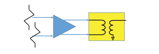
A more classical approach to dealing with correlated DUT noise outputs is to send them first to a balun (or a combiner in more general terms). If the line lengths to the balun are equal and the balun balance is ideal, then a differential signal is generated for conventional 2-port noise analysis and only the insertion loss of the balun must be de-embedded (e.g., [5]-[6]).
Using a Balun for Differential Noise Figure Measurements
The use of a balun (or combiner more generically) is a useful measurement method to get differential (or common-mode) noise figure when coupled with de-embedding.
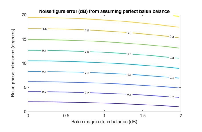
If the balance of the combiner/balun is less than ideal, some errors can be introduced. On a simple level, for noise figure, the gain of the balun is described by Sd1, so asymmetries will be corrected for directly. Noise power, however, is also affected. Similar to the discussion in the previous section, the difference between correlated and uncorrelated noise power is the correlation term. One measure of the effect of balun irregularities may then be the change they introduce into the correlation term. A simulation was run where varying degrees of imbalance were inserted and the fractional change in the correlation term was computed (see results in Figure: Noise Figure Error from Neglecting Balun Imbalance). Relatively large amounts (up to 1 dB) of amplitude imbalance did relatively little, but 10 degrees of phase imbalance caused about ~0.5 dB noise figure error. At least for high-frequency broadband baluns, such a level of imbalance is not unusual. Considering also the lines connecting the DUT to the balun (assuming they are not integrated on the same chip, in which case this can indicate the sensitivity to layout): 10 degrees of phase difference at 70 GHz corresponds to about 120 mm length difference with an air dielectric (and less on any substrate). Thus some means of correcting for imbalance might have a detectable effect on overall measurement accuracy.
Noise Figure Error from Neglecting Balun Imbalance
The calculations assume minimal ohmic balun insertion loss, and neglect mismatch.
.
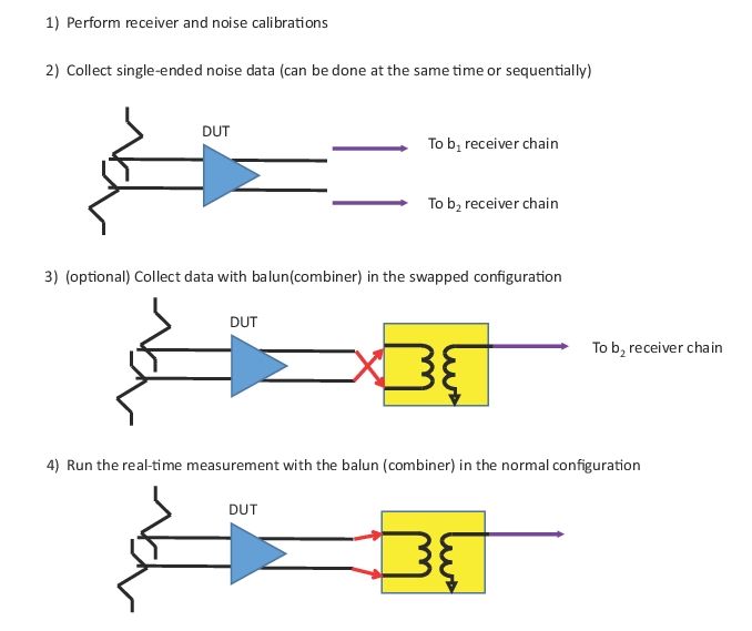
Conceptually, one can arrive at the correlation term by separately measuring the single-ended noise powers from the DUT and removing their effects after propagating them through the S-parameters of the balun (e.g., [7]). This does leave one additional layer of ambiguity on how the noise powers combine in the balun, since the real and imaginary parts of correlation can co-mingle. If one can assume that the imaginary part is negligible, only one balun-based measurement (this updates the display real time) is required. To fully treat the imaginary part, a second swapped-measurement with the balun in place can be done. This swapped measurement is stored, much like a noise calibration step, and should be updated with DUT changes. In both cases (with or without the swapped measurement), the single-ended DUT noise measurements must be stored, also like noise calibration steps, and these should also be refreshed with DUT changes. The sequence of measurements is shown in Figure: Measurement Sequence for the Combiner Method.
Some notes on this measurement:
• The balun (combiner) must be pre-characterized and an .s3p file stored with port 3 as the defined common port. A port swap tool is available for files stored with some other port configuration. Interpolation and (flat line) extrapolation will be used for frequency lists that do not match the current list.
• Step 2 (and 3 if the second combiner measurement is used) should be repeated if the DUT or its bias state is changed.
• Only the b2 receiver chain is used for the combiner measurements. While the b1 receiver is used for the single-ended measurements, the same pre-amplifier/filter assembly can be used on b1 and b2 inputs since these single-ended measurements do not have to be performed simultaneously.
Measurement Sequence for the Combiner Method
Step 3 is optional when the double-combiner measurement sub-method is selected, but can improve accuracy, particularly for DUTs with partially correlated outputs.
• There are no particular constraints on the balun parameters, but if the insertion loss is very high, low DUT noise figures (or moderate noise figures on very low gain DUTs) may have higher uncertainties. The algorithm has to work harder the more non-ideal the balun/combiner is, so the characterization accuracy of that balun becomes more important in those cases.
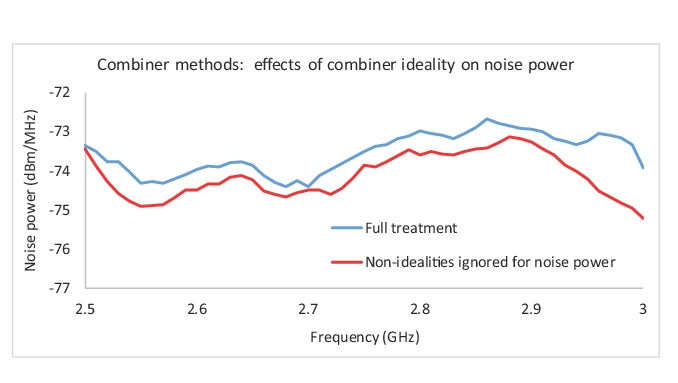
Consider an example measurement that uses the full characterization of the combiner to calculate the correlation, as just discussed. The resulting noise power is plotted in Figure: Noise Power Examples using Balun and Classical Combiner Approaches, where it is contrasted with a measurement where the noise power was just measured directly and the loss (in a differential sense) of the combiner simply de-embedded. Note that gain definitions do not play a role in these plots, as it is simple noise power referenced to a common reference plane (and de-embedding would not be able to treat correlation differences) but the errors do reach 0.5 dB or more in places, which is not entirely inconsistent with Figure: Noise Figure Error from Neglecting Balun Imbalance. The net amount of difference is a function of both the non-idealities in the combining structure and the degree of correlation in this particular DUT output. As always, noise power (in excess of calibration values) will propagate to noise figure on a dB-for-dB basis.
Noise Power Examples using Balun and Classical Combiner Approaches
An example measurement result of noise power for a differential amplifier using the balun (combiner) method of this section (blue/upper trace), and for a more classical combiner approach (red/lower trace) where the noise power from the combiner is measured directly and the loss of the balun de-embedded.
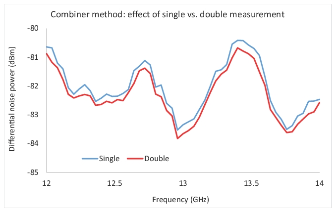
The effect of the using the single or double combiner measurement can be more subtle depending on the details of the DUT correlation. A relatively representative example measurement of a highly correlated DUT is shown in Figure: Noise Power Examples Using Balun and Single Combiner Methods for both approaches to incorporate balun non-idealities. The average difference over the bandwidth was ~0.3 dB, which is higher than the repeatability level for this DUT measurement (~0.1 dB) but less than the absolute uncertainty levels and less than the differences seem in Figure: Noise Power Examples using Balun and Classical Combiner Approaches (where the balun was treated as ideal for correlation purposes). There may be devices with different correlation structures where the single/double difference could be larger.
Noise Power Examples Using Balun and Single Combiner Methods
An example measurement result of noise power for a differential amplifier using the balun (combiner) method of this section, and a single combiner/balun measurement (blue), or the double measurement (red), which makes fewer assumptions about the nature of the correlation function.
• Perform a power calibration on port 1 (if desired) at a sufficiently low level that the composite receivers will not compress. Perform a receiver calibration (using this power calibration if desired) on both receiver paths (the receiver and correlation calibrations can be done simultaneously using the checkbox in the dialog. These calibrations can be done while in the noise figure application or can be recalled.
• Perform a noise calibration on both receiver paths with terminations attached to the receiver inputs.
• Load DUT S-parameter or gain data.
• Connect DUT (without the combiner/balun present) and collect b1 and b2 noise data (can be done at the same time).
• If the ‘double’ combiner measurement was selected, connect the combiner/balun with the inputs swapped (relative to the desired connection) and collect the data. If ‘single’ was selected, skip this bullet.