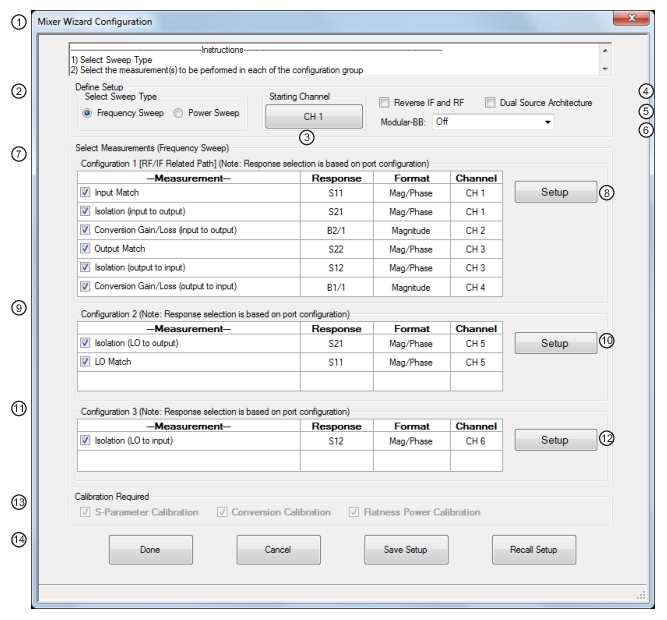
The multiple channel mixer wizard is, in some sense, a natural extension of the single channel setup method introduced previously. The difference here is that multiple measurements are orchestrated for the user in different channels with the corresponding sweeps already setup and the calibrations suggested. The main configuration dialog is shown in Figure: Mixer Wizard Configuration (Frequency Sweep) Dialog Box—Control Areas (1 of 2). In addition to some of the controls discussed previously are a list of possible measurements separated into 3 groups: between input and output, between LO and output, and between LO and input. The three groups require different connections since the LO port needs access to receivers in the second two sets. All measurements can be set up at once, but the results from different groups will only be meaningful if the DUT is connected correctly.
All of the measurements shown have been discussed previously, but now they are automatically assigned to different channels that will control the different sweeps. To see this concept, suppose one requests forward conversion gain/loss (input to output), isolation (input to output) and isolation output to input. The first measurement requires the source to sweep over the input frequencies while the receiver sweeps over the output frequencies. The second measurement requires both the source and receiver to sweep over the input frequencies. The third measurement requires both the source and receiver to sweep over the output frequencies. By placing these three measurements in different channels, all the measurements can be completed in one ‘super sweep’ without user intervention and all of the results displayed at once.
There is a Starting Channel button on this dialog to indicate which channel should have the first measurement and the others will increment from there. While the default is to start with channel 1, the user may have setups in one or more channels that they would like to keep sweeping in addition to those measurement orchestrated by the mixer wizard.
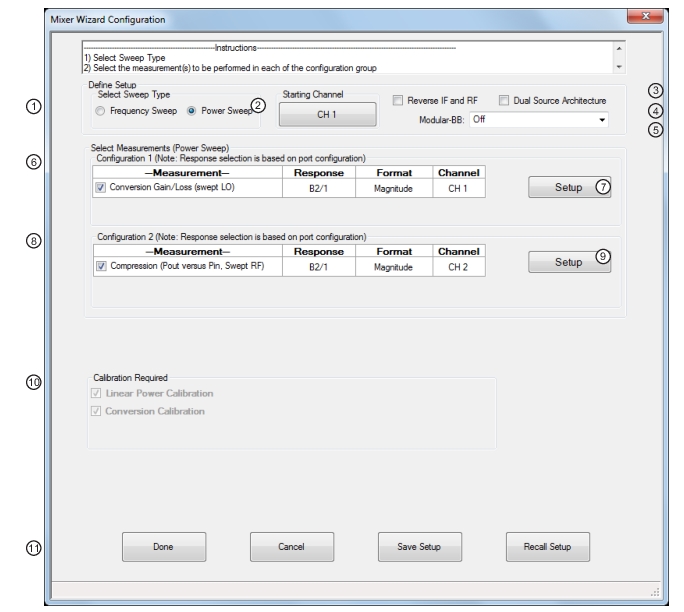
The power and frequency setup dialogs are essentially the same as for the single channel setup system and will not be repeated here. Minor differences can be analyzed in the operating manual or the UI guide. For the power sweep case, the choices are more limited and are shown in Figure: Mixer Wizard Configuration (Power Sweep) Dialog Box—Control Areas. As had been discussed previously, conversion gain as a function of input power (compression) may be of interest as can conversion gain versus LO power (looking for LO saturation while the input power is constant). Unlike the manual method in the single channel setup, here the swept power on the respective port will be requested.
.
Mixer Wizard Configuration (Frequency Sweep) Dialog Box—Control Areas (1 of 2)
1. Dialog Box
2. Select Sweep Type (Frequency or Power Sweep).
3. Channel Start Selection
4. Reverse IF and RF—Default is RF as input and IF as output. Toggles to RF as output and IF as input.
5. Modular Broadband selection dropdown—Only for MS4647B VNAs with Option 8x BB/m-Wave System.
6. Dual Source Architecture (Only for MS464xB VNAs with Option 31) Note that when this feature is selected, the measurement selections change as shown in the figure below.
7. Configuration 1—Conversion Gain/Loss Swept LO— RF/IF Related Path—Select any combination of measurements. Channels are automatically assigned based on Starting Channel.
8. Setup Button—Links to Configuration 1 Dialogs to configure mixer and VNA ports, external sources, frequency, and power levels.
9. Configuration 2—Compression Pout versus Pin Swept RF—Select any combination of measurements. Channels are automatically assigned.
10. Setup Button—Links to Configuration 2 Dialogs to configure mixer and VNA ports, external sources, frequency, and power levels.
11. Configuration 3—Isolation—LO to Input Available Measurement
12. Setup Button—Links to Configuration 3 Dialogs to configure mixer and VNA ports, frequency, and power.
13. Calibration Required Area
14. Dialog Controls
Mixer Wizard Configuration (Power Sweep) Dialog Box—Control Areas
1. Select Sweep Type
2. Select Starting Channel
3. Reverse RF and IF—Standard is RF is input and IF output. Reverse is RF as output and IF as input.
4. Modular Broadband selection dropdown
5. Dual Source Architecture (Only for MS464xB VNAs with Option 31) When this feature is selected in Power Sweep mode, the measurement selections do not change.
6. Configuration 1 Measurements for Conversion Gain/Loss Swept LO.
7. Setup button to Configuration 1 dialogs
8. Configuration 2 Measurements for Compression Pout versus Pin Swept RF.
9. Setup button to Configuration 2 dialogs.
10. Calibration Required Area display.
11. Dialog control buttons.
Note
An additional point for all multi-channel mixer setups is that the input port frequency range must have a start frequency less than the stop frequency. The output and LO ports are allowed to sweep backwards.
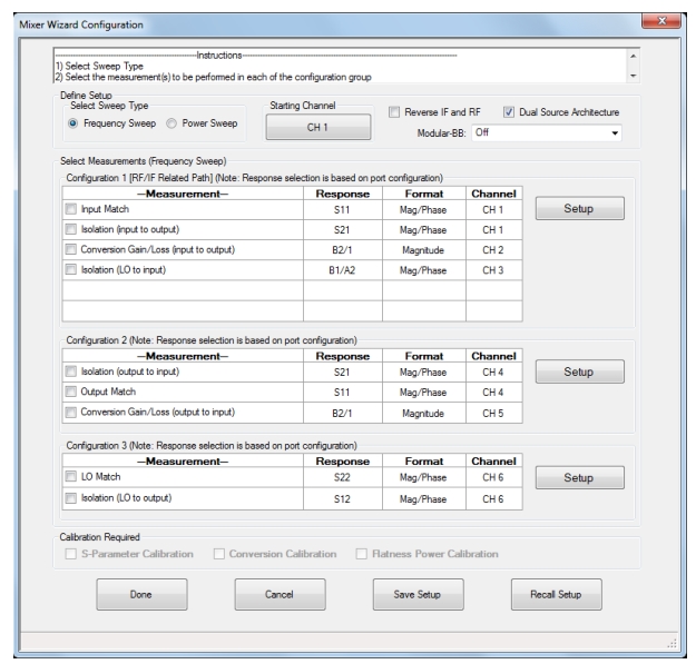
As with the active channel mixer setups, additional features can become available, and additional limitations incurred, when using the second source and loops (Option 31 and one of Options 51/61/62). In the setup dialog, there is a Dual Source Architecture checkbox that will only be visible when the above options combination exists. By selecting this option, the user is indicating the desire to use the second source as an LO. This selection is mutually exclusive with the Enable Modular-BB selection.
When selected, the measurement choices change somewhat as shown in Figure: Multi-channel Mixer Setup Dialog with Dual Source Architecture Selected because the use of the second source requires some measurements to move to different setup groups. As with the active channel case, when the second source is used as an LO (the checkbox selected in this case), the enhanced match calibrations will not be available for the conversion gain/loss measurements since full reversing measurements (that would use the second source) required for those calibrations are not possible with this type of setup.
Multi-channel Mixer Setup Dialog with Dual Source Architecture Selected
The multi-channel mixer setup dialog with Dual Source Architecture selected is shown here for the case of using the internal second source as a DUT LO.
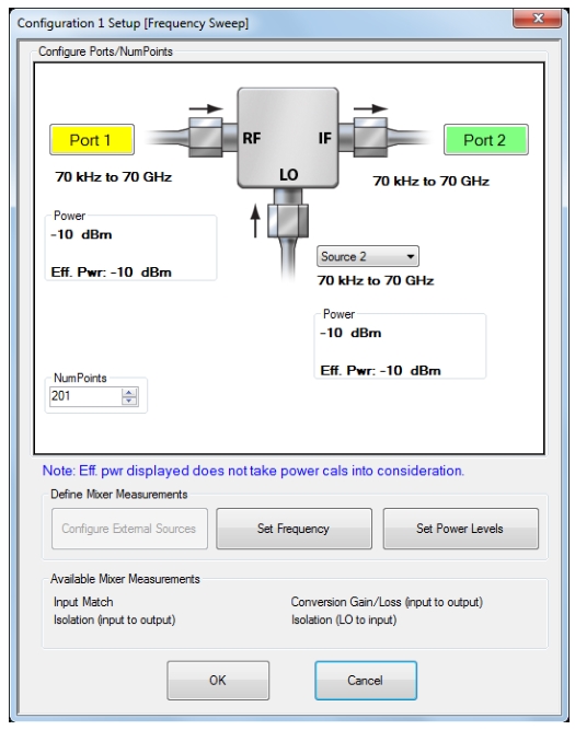
Configuration 1 Setup Sub-dialog for Dual-source Selection 2-Port Case
The input and output are constrained to be either port 1 or port 2. The LO is forced to be either source 1 or source 2. The latter case corresponds to the Case (a) setup from Figure: Setups for Source 2 and Port 2 LO Drive. Again, since the leveling circuitry is behind the source loop (used for source access), full power control and power calibrations will be available for the LO. As in Figure: Setups for Source 2 and Port 2 LO Drive, it is recommended to terminate the unused loop port to improve the raw match that the DUT output will see looking into port 2. Also, the RF-IF assignments will swap if the Reverse IF and RF checkbox has been selected. If it is desired to use an external source for the LO (or input), then both internal sources are not required and the Dual Source Architecture checkbox should not be selected.
With 4-port single-source systems, the multi-channel setups are basically the same as for 2-port single-source cases except any of the ports can be used as input and output (and, again, an external source can be used as input with some calibration limitations). The dual source architecture selection has slightly different effects.
• For setups 1 and 2, the input, output and LO can be any port, but there are some combination restrictions. If the LO is port 3 or port 4, then the input and output should be selected amongst port 1 and port 2. If the LO is port 1 or port 2, the input and output should be selected amongst port 3 and port 4.
• For setup 3 (dealing with LO paths), if the LO is port 1 or port 2, b1 is not allowed for the output. If the LO is port 3 or port 4, b2 is not allowed for the output.
Configuration 1 Setup Sub-dialog for Dual-source Selection 4-Port Case