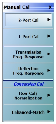
While many of the mixer calibration topics with regard to conversion gain/loss have already been discussed in passing, it may be helpful to review some of their attributes. When a mixer has been set up using the tools described, the manual calibration menu changes to that shown in Figure: The MANUAL CALIBRATION Menu When in Mixer Mode.. The two bottom buttons describe two options
• Rcvr Cal/Normalization: A receiver cal is performed (as part of the ‘thru’ step) to establish absolute power accuracy and then a normalization is done to take into account the power incident on the mixer input port. A separate receiver calibration does not need to be performed. A power calibration is recommended for increased accuracy and this must be executed separately. Ideally, the power calibration would be performed over input and output frequency ranges (using segmented sweep can save time). Note that for mmWave applications, the system should be in the proper leveling mode when the calibration is performed (for example, RF leveling for the 3743x modules).
This calibration is very fast to perform and only one sweep is needed during the measurement, but as will be discussed in the uncertainties section, does become less accurate as the DUT match degrades.
• Enhanced Match: This is the process that was described in Mixer Measurements where match components at the input and output of the mixer are taken into account. This calibration is structured very much like a traditional full 2-port calibration, except several different frequency lists are employed: input range→input range, input range→output range, output range→output range.
The MANUAL CALIBRATION Menu When in Mixer Mode.
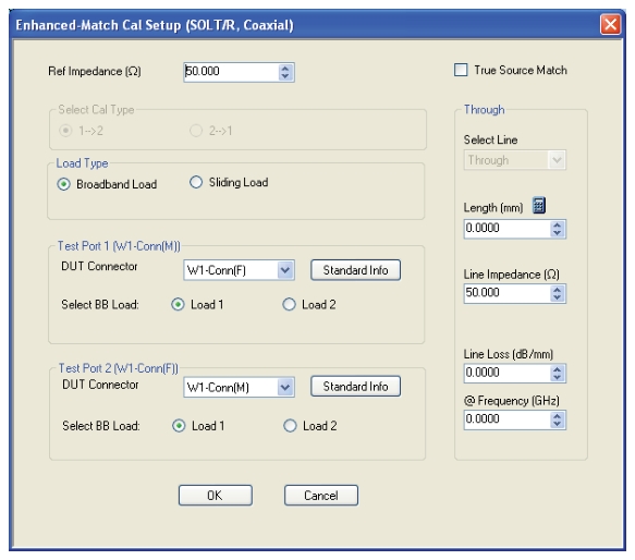
The enhanced match calibration can be performed in any media type and with any of the defined-standards calibration algorithms. An example of the setup dialog is shown in Figure: Example Enhanced Match Cal Setup Dialog. Note that the direction of the calibration is fixed by the input/output relationship defined in mixer setup and reciprocal connections are not available due to the power transfer computation requirement. The True Source Match checkbox was described in Mixer Measurements and refers to a different set of internal calibration steps used, particularly for millimeter wave applications, when a more accurate measurement of the driving match that the DUT sees is needed. This selection will almost never make things worse (one exception being if the driving network is marginally stable when out-of-band due to the addition of an amplifier in the system loops) and can improve conversion loss flatness at higher frequencies.
Example Enhanced Match Cal Setup Dialog
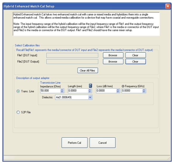
When an enhanced match calibration is being applied, one may note that three sweeps are required. These are used to get DUT input and output match (non-frequency converting measurements in different ranges) as well as conversion. In certain cases, one wishes to perform an enhanced match calibration but the input and output media of the DUT are different (for example, waveguide and coax) and perhaps different algorithms need to be used on those ports (for example, SSLT and SOLT). Analogous to the hybrid calibrations referenced for non-frequency converting measurements earlier in this guide, there is a hybrid enhanced match calibration to handle this case for mixers. The dialog, accessible from the ALTERNATIVE CALS menu (via the CALIBRATION menu, is shown in Figure: Hybrid Enhanced Match Calibration Setup Dialog.
Hybrid Enhanced Match Calibration Setup Dialog
The Hybrid Enhanced match calibration dialog is shown here. This approach is helpful for mixers with different connection media at input and output (such as a waveguide input, but a coaxial output).
The process, again analogous to regular hybrid calibrations, is that one performs an enhanced match cal in each of the media types (and/or algorithm choices), and this utility combines them. The key point is that each calibration is not frequency converting, so the relevant pieces of the calibration for each media type can be extracted to form the hybrid calibration.
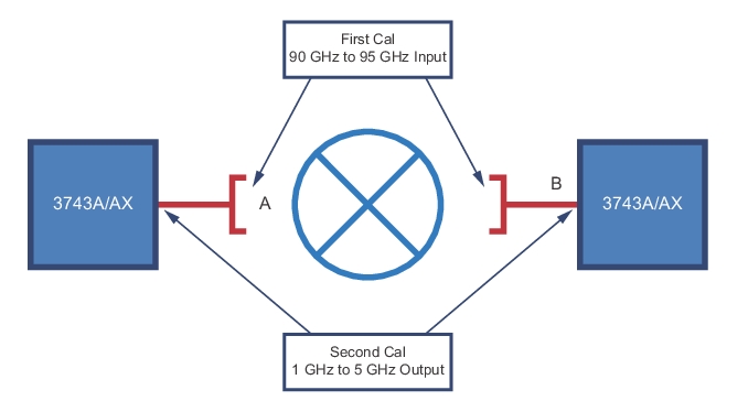
Consider an example using the ME7838A/AX broadband system.
• Input 91-95 GHz in WR-10 (will need to use a SSLT calibration kit at this plane)
• Output 1-5 GHz in coax (will use an SOLT calibration kit at this plane)
• LO (not shown) fixed at 90 GHz
Two complete enhanced match calibrations are completed where the ME7838A/AX system (using 3743A/AX mmWave modules) natively use 1 mm connectors. Coax-to-waveguide adapters are in place for the first enhanced match calibration and are removed for the second. The same mixer frequency plan is used for each calibration. Schematically, the calibration reference planes are as shown in Figure: Example Hybrid Enhanced Match Calibration Setup. We desire the final reference planes to be at A and B.
Example Hybrid Enhanced Match Calibration Setup
During the first (waveguide) calibration, one may notice some data being acquired that is nonsensical since it is below the waveguide cut-off. This ends up being OK since those measurements are not used in the hybrid computation, but leaving them in the execution sequence allows the instrument to relatively easily offer almost all calibration permutations. When the two calibrations are performed and saved, they can be loaded into the dialog of Figure: Hybrid Enhanced Match Calibration Setup Dialog.
The final step is a description of the output adapter, which is needed to get the power calibration transfer as accurate as possible. A simple transmission line model can be used or a .s2p file (covering the input frequency range, preferably) can be entered. In the latter case, interpolation and flat-line extrapolation of the file will be used when the frequency lists do not match. Normally this adapter loss is much less than 1 dB and it does not have a great effect, but there are exceptions based on the user setup.