Pulsed S-parameter and related measurements are critical for many common applications:
• Tests of system and subsystems designed to operate in pulsed conditions.
• Pulsed system and subsystem measurements that may be needed to examine phase and amplitude distortions at pulse onset or droop later in a pulse, as well as in cases where the subsystem was designed to operate pulsed.
• Measurement of devices and components that are designed to operate in pulsed conditions.
• Device characterization, where pulsed operation is required for thermal reasons (for example, un-mounted power devices).
• Device characterization, where pulsed operation is required to explore certain device characteristics. Trapping and thermal parameter characterization are two common tasks that benefit from pulsed measurement.
When making pulsed measurements for the applications listed above, many aspects of the test system may be of interest. A VNA is typically used when there is a need for measurement correction, phase data, or a more integrated test suite.
All of the standard VNA measurement parameters, calibration types and post-processing methods still apply to pulsed measurements, but there are many subtle factors affecting measurements that will be discussed and explained in this chapter.
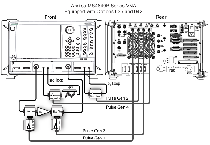
Because of the wide array of applications and Devices Under Test (DUTs), many test configuration varieties involving pulsed stimulus, receiver gating, and pulsed DUT bias and control may be of interest. An example configuration is illustrated in Figure: A Comprehensive Pulsed Measurement Setup, and presumes S21 as the measurement of primary interest. Full correction is possible in this setup. Previous generations of Vector Network Analyzers have relied on receiver-side pulsing to control the measurement.
Note
Intra-pulse behaviors on the reflection parameters may often be ignored, depending on the measurement methodology. Figure: A Comprehensive Pulsed Measurement Setup illustrates a setup without b1 modulation.
A Comprehensive Pulsed Measurement Setup
Source RF pulses, multiple bias pulses, and DUT control pulses (not shown) may be needed.