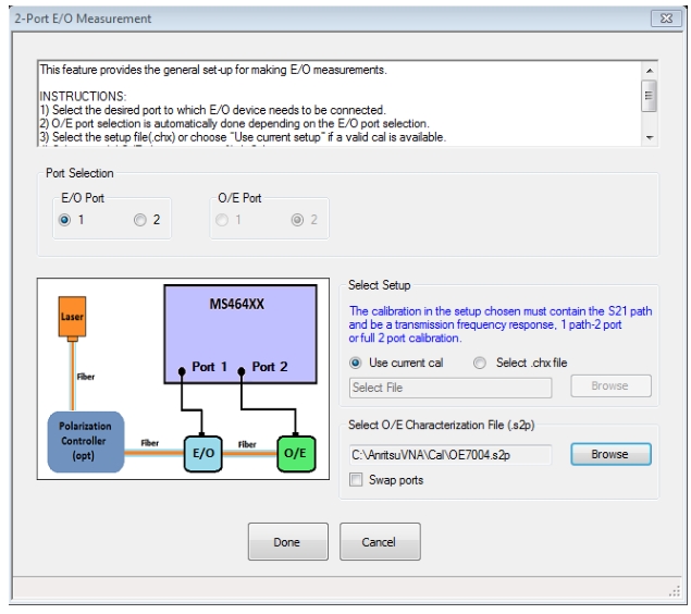
With the physical setup described, the next task is really how to interface with the measurement utilities. Consider first the case of a 2-port E/O measurement where one has a characterized O/E device (such as the MN4765X). The dialog for this measurement is shown in Figure: Dialog for 2-port E/O Measurements (the system automatically detects if it is a 4-port configuration in which case one of the later dialogs would be displayed instead). One choice that has to be made is the port configuration. The default is to have the E/O device connected to port 1 of the VNA, but this can be changed.
Navigation to 2-Port OPTICAL MEASUREMENT Dialog Box
The other major requirement is a 2-port VNA calibration. This dialog assumes that the calibration has already been done with the desired method, frequency range, etc. and saved (using Save Setup under the File menu) as a .chx file or is available in the current setup. Most of the setup parameters are obvious:
• Frequency Range and Number of Points (dictated by the bandwidth of the DUT among other test requirements)
• Power Level (this depends on the linear drive range of the modulator as discussed above and the maximum available power of the VNA, which varies with options. Generally, the higher the better within those limits for best signal-to-noise ratio)
• IF Bandwidth and Averaging (trade-off between measurement time and trace noise. Generally 10-100 Hz IFBW is recommended for very wideband devices since the conversion losses tend to be high and the signal-to-noise ratio is stressed). Averaging can be added for additional trace noise reduction but there is a point of diminishing returns beyond about 10 sweep-by-sweep averages or if IFBW/(pt-by-pt averages) falls below 1 Hz.
• Calibration Method The only requirement is that the calibration contain a transmission path that match the E/O → O/E path (anything beyond that is acceptable). Some of the choices are:
E/O Port = 1
Forward transmission tracking (1→ 2)
1 path – 2 port forward (1→ 2)
Full 2 port calibration
E/O port= 2
Reverse transmission tracking (2→ 1)
1 path – 2 port reverse (2→ 1)
Full 2 port calibration
Any calibration algorithm can be used (SOLT, SOLR, LRL, LRM, etc.) as appropriate.
If the current setup is not to be used, the desired setup file can be loaded in the dialog of Figure: Dialog for 2-port E/O Measurements, as can the O/E characterization file (in a .s2p file format). Note the Swap ports checkbox availability near the characterization portion of the dialog box. It is always assumed that the dominant path in the characterization file is the S21 parameter. If the file was constructed differently (e.g., S12 was the measurement path for the calibration device), then selecting the checkbox will force the instrument to reorder the ports in the file before processing.
When Done is selected on this dialog, the de-embedding is applied and the resultant calibration left on the system includes the shifted reference plane as suggested by Figure: Reference Plane Placement. This state can be saved as a new setup file (again using the Save Setup command under the File menu) if desired. Note that to go back to the non-de-embedded state, one can recall the old setup file that was just loaded in the dialog box. At this point, one can make measurements of any number of E/O devices and save the results using any of the usual techniques.
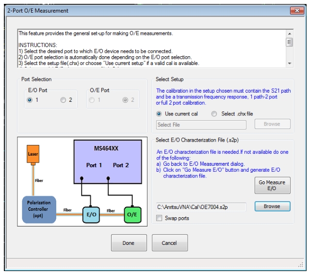
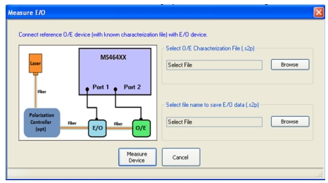
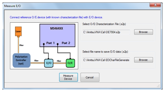
The O/E measurement setup is quite similar and that dialog is shown in Figure: Dialog for 2-port O/E Measurements. The difference, of course, is that an E/O characterization file must now exist. One can generate it using the previous procedure and saving the measurement result as a .s2p file or one may already have a characterization file for the E/O device. If this is not the case, a shortcut is provided to help generate an E/O characterization file with less work. This path is triggered with the Go Measure E/O button which will bring up the sub-dialog of Figure: Help in Doing the Intermediate Measurement with the Help of a Calibration O/E Device.
Assuming one has an O/E calibration device (such as the MN4765X), this Go Measure feature allows one to load that photodetector characterization file and use the setup file found on the main E/O dialog to do a quick measurement of the modulator (or assembly). The sub-dialog also has a field to save this new E/O characterization file.
When completed, one can go back to the previous dialog and select Done. The resultant setup will now have the Port 1 reference plane moved to after the modulator so one can now measure any number of new O/E devices. Again, the final setup (with shifted reference planes) can be saved as can any new measurement data of the O/E devices.
Dialog for 2-port O/E Measurements
Help in Doing the Intermediate Measurement with the Help of a Calibration O/E Device
When measuring O/E devices, the characteristics of the E/O device must be known. If a file does not already exist, this dialog can help in doing the intermediate measurement with the help of a calibration O/E device such as the MN4765X.
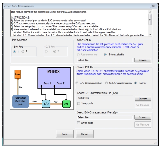
The O/O measurement is somewhat like the E/O and O/E measurement setups in series: both the detector and the modulator must be de-embedded to leave the reference planes in the optical domain. As suggested by Figure: 2-port O/O Measurements Dialog, if both .s2p files exist, their file names can be entered directly and the de-embedding will proceed. If one of them does not exist (usually the modulator file but either is allowed), it can be measured on the fly much like with the Go Measure process in the O/E measurement previously. This Go Measure process (dialog shown in Figure: Help in Doing the Intermediate Measurement with the Help of the File for a Second Device) allows one to enter the known device’s file and to define the file name for the newly created file. Note that this Go Measure process assumes the modulator and detector are directly connected together in an optical sense and this defines the reference plane locations. In some sense, this step is like an optical normalization.
Note that the .s2p file name for the known device is assumed to be the same as that used on the main O/O dialog as this device normally doesn’t change between Go Measure and O/O configuration steps. If a different device is to be used, the file name on the main O/O dialog can simply be changed after the Go Measure process is completed.
2-port O/O Measurements Dialog
Help in Doing the Intermediate Measurement with the Help of the File for a Second Device
When measuring O/O devices, the characteristics of both O/E and E/O devices must be known. If a file for one does not already exist, this dialog can help in doing the intermediate measurement with the help of the file for the other device (usually a calibration O/E device such as the MN4765X). At least one converter must have a .s2p file to do the measurement.
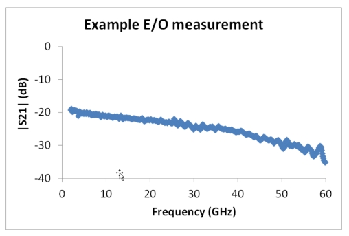
Example E/O Measurement
As an example, consider the following setup:
• 2 GHz to 60 GHz, 10 Hz IFBW, power –10 dBm, no averaging.
• A full 2-port SOLT calibration is performed using a 3654D Calibration Kit.
• The resulting setup file is saved as setup.chx. This setup file will include all of the above parameters including the calibration data.
• The optical assembly is hooked up with the modulator-under-test connected to Port 1 and an MN4765X O/E calibration module connected to Port 2 of the VNA. The laser is powered up after setting up bias control on the modulator and applying bias to the MN4765X (and, of course, connecting the fiber).
• The E/O measurement utility is invoked using the default port assignment, loading the .chx setup file and loading the characterization file of the MN4765X. Upon selecting Done on the dialog, the resulting S21 measurement reflects the conversion behavior of the modulator and is shown in Figure: Results of an Example 2-port E/O Measurement. In this case, there is about 10 dB of roll-off over the bandwidth of the measurement.
Results of an Example 2-port E/O Measurement
The results of an example 2-port E/O measurement are shown here using the procedure discussed in the text.