In normal operation, leveling is controlled by a detector situated in the coupled reference arm (or at the source itself for frequencies under 2.5 GHz). There are cases when it might be useful to have the detection point be somewhere else:
• If an external pre-amplifier is being used (in the source loop or at the VNA test port), it may be useful to level at the output of that amplifier to account for the drift of that amplifier. In this case, usually a coupler+detector pair would be placed somewhere after the amplifier although some candidate external amplifiers have built-in power detection.
• The DUT drive chain may involve a frequency converting stage and it may be desired to level at that converted reference plane.
• There may be a very long cable run to the DUT and maintaining a specific drive to the DUT is important. In this case, it may be desirable to place a remote detector to level at a point closer to the DUT (and since the detected return signal is at much lower frequencies, it may be less impacted by the distance but one does still have to be aware of noise ingress and IR losses).
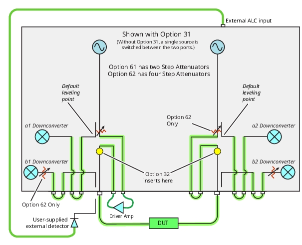
The external ALC port on the rear panel is also used for broadband/millimeter wave applications (see Multiple Source Control (Option 7) of this guide) but is activated globally with Option 53 (note that when in 3739 broadband/mmWave modes, the external ALC connector takes on the mmWave leveling role). As suggested by Figure: Option 53, External ALC Access, the default leveling point is before the source loops. This is to prevent the power from railing to a high level when the loop is opened under normal operating conditions. However, it may be desirable to level after any driver amplifier that may be inserted into the loop. An example setup is shown in Figure: Option 53, External ALC Access. Note that either an external coupler and detector arrangement is needed or an external detector must be connected to the reference loop path via a splitter, hybrid, or similar device. While many detectors can be used, the following should be kept in mind:
• The detector must be negative going with an allowed range of about 0 to –1.3 V (–1.3 V corresponding to highest power observed). The damage level is larger (> +15 V and < –15 V) but the internal DAC comparison circuit will no longer respond for voltages more negative than about –1.3 V or for positive voltages.
• The external ALC input has a floating ground with impedance to chassis ground of ~3 kΩ. The effective input impedance is ~2 kΩ.
• When activated, the power level may be very low or very high since the system has no a priori knowledge of the detector’s characteristics. Measurement or user power calibration of the port power should be done before connecting a DUT.
• If the detector is not connected and external ALC is enabled, the system will have no way of knowing of the absence and that power will rail to a high level. Again, it is especially important when using external ALC to verify power delivery and control before connecting a sensitive DUT.
• Since external leveling is most commonly needed with active applications, external ALC access requires the presence of Option 61 or 62 (loops with step attenuators) discussed earlier in Option 61/62 and Step Attenuators.
Option 53, External ALC Access
An example setup using an external ALC input is shown here.
As might be expected, user power calibrations are quite important when using external ALC. As discussed with option 51, use the Entered Power value and the Target Power value to not only get the desired power but to give the instrument a hint about how much drive is going to be needed to get to the target level. Depending on the sensitivity and range of the detector employed, the power range that can be calibrated may be limited so some experimentation may be required.
The External ALC use is activated from the Other Setup submenu under the Power menuas shown in Figure: ALC Input Control Selection. Again, this behavior is overridden when in the broadband/mmWave modes that use the external ALC port for mmWave power control. When in one of those 3739 modes, the ext. ALC connector on the VNA should be reconnected to the 3739X test set.
ALC Input Control Selection
External ALC control is activated under a power submenu. This menu button is only available with Option 53 or Option 8x installed.