This test verifies that each individual receiver operates properly. Measurement calibration of the system is not required for this test. This test requires that you press specified front panel keys, or use a mouse to make choices from the displayed menus and is valid for all instrument model and option combinations. The key and menu selections used in this test are shown below.
Procedure
1. Connect Test Ports 1 and 2 together using a high-quality through line.
2. At the top of the display, select MENU BAR | Utilities | System. The right-side SYSTEM menu appears:
• Click Setup. The SETUP menu appears.
• Click Preset Setup. The PRESET SETUP menu appears.
• Select Default.
• The default setting associates both the front panel Preset Key and the MENU BAR | Utilities | Preset command with the factory-default preset configuration.
3. Reset the VNA by pressing the front panel Preset Key.
• The VNA resets to the factory-default as-shipped configuration.
• The right-side menu returns to the MAIN MENU.
4. At the top of the display, select MENU BAR | Utilities | System.
• The right side SYSTEM menu appears.
5. On the right-side, select SYSTEM | Utility | UTILITY | Factory Receiver Cal and toggle the Factory Receiver Cal button to OFF.
Check Frequency and Set Power
6. On the right side MAIN MENU, select Frequency.
a. The FREQUENCY menu appears.
b. Observe the displayed Frequency menu.
c. Note that the Start and Stop values are the low-end and high-end frequencies.
7. At the top of the display, select MENU BAR | Channel | Power.
a. The right side POWER menu appears.
b. Click on the Port 1 Power button.
c. In the displayed field toolbar, enter -10.0000 dBm.
d. Click the X at the end of the toolbar to close it.
Set Channel and Trace Display
8. Select the upper left LCD channel using the mouse by clicking on Tr1 S11 Refl Smith Imped.
• The trace name has additional resolution and unit information appended to the displayed label.
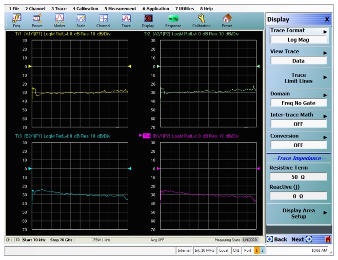
9. At the top of the display, select MENU BAR | Trace | Display. The right side DISPLAY menu appears.
a. Click the Trace Format button, the TRACE FORMAT menu appears.
b. Select Log Mag.
10. On the icon toolbar, select the Responseicon.
a. The RESPONSE menu appears.
b. Click on User-Defined, the USER DEFINED menu appears.
c. Click on Numerator and on the NUMERATOR menu, set it to A1.
d. Click on Denominator and on the DENOMINATOR menu, set it to 1.
e. Set Driver Portto Port 1.
Select Lower Left Channel
11. Select the lower left channel by clicking trace label that starts with Tr3 S21 Trans LogM+P.
• The trace name has additional resolution and unit information appended to the displayed label.
12. At the top of the display, select MENU BAR | Trace | Display. The right side DISPLAY menu appears.
a. Click on the Trace Format button, the TRACE FORMAT menu appears.
b. Select Log Mag.
13. On the icon toolbar, select the Responseicon. The RESPONSE menu appears.
a. Click on User-Defined, the USER DEFINED menu appears.
b. Click on Numerator and on the NUMERATOR menu, set it to B2.
c. Click on Denominator and on the DENOMINATOR menu, and set it to 1.
d. Set Driver Portto Port 1.
Select Upper Right LCD Channel
14. Select the upper right LCD channel using the mouse by clicking on Tr2 S12 Trans Log M+P.
• The trace name has additional resolution and unit information appended to the displayed label.
15. At the top of the display, select MENU BAR | Trace | Display. The right side DISPLAY menu appears.
a. Click on the Trace Format button, the TRACE FORMAT menu appears.
b. Select Log Mag.
16. At the top of the display, select MENU BAR | Trace | Response.The right side RESPONSE menu appears.
a. Click on User-Defined, the USER DEFINED menu appears.
b. Click on Numerator and on the NUMERATOR menu, and set it to A2.
c. Click on Denominator and on the DENOMINATOR menu, set it to 1.
d. Set Driver Portto Port 2.
Select Lower Right Channel
17. Select the lower right channel by clicking on Tr4 S22 Refl Smith Imped.
• The trace name has additional resolution and unit information appended to the displayed label.
18. On the top menu bar, select MENU BAR | Trace | Display. The right side DISPLAY menu appears.
• Click on the Trace Format button. The TRACE FORMAT menu appears.
• Select Log Mag.
19. On the top menu bar, select MENU BAR | Trace | Response.The RESPONSE menu appears.
a. Click on User-Defined, the USER DEFINED menu appears.
b. Click on Numerator and on the NUMERATOR menu, and set it to B1.
c. Click on Denominator and on the DENOMINATOR menu, and set it to 1.
d. Set Driver Port to Port 2.
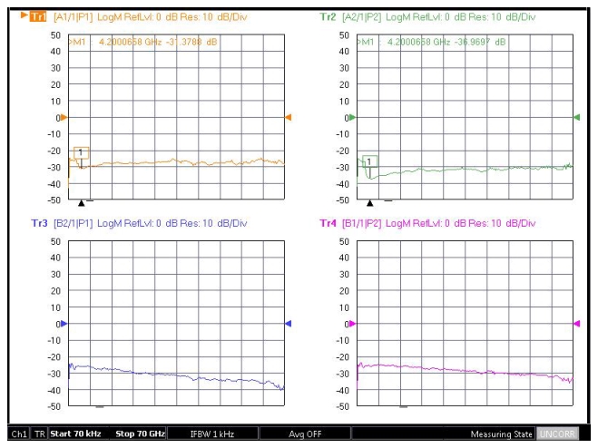
Review Amplitude Slopes for Maximum and Minimum Values