The interface between the VectorStar MS464xB Series VNA and other devices on the GPIB is via a standard 24-wire GPIB interface cable. This cable uses a double-sided connector where one connector face is a plug and the other a receptacle. These double-function connectors allow parallel connection of two or more cables to a single instrument connector.
Caution
When two or more cables are connected in parallel, do not bend the attached connectors as this could damage the rear panel GPIB Port connector.
Configuring the Dedicated GPIB Port
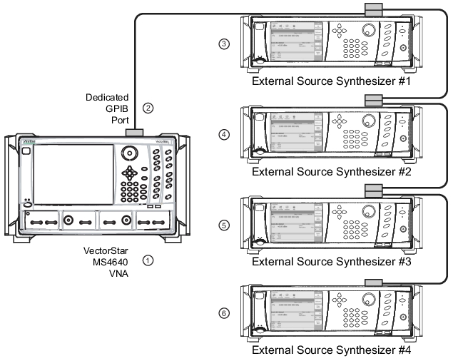
Use this procedure to set up the dedicated GPIB port to control other GPIB devices such as Power Meters or Signal Generators by using the VNA rear panel Dedicated GPIB Port. An example of a complex GPIB configuration with the VNA as the GPIB controller is shown in Figure: VNA as a Remote GPIB Controller for Synthesizers.
VNA as a Remote GPIB Controller for Synthesizers
1. VectorStar MS464xB Series VNA.
2. Rear Panel Dedicated GPIB Port and GPIB Cable.
3. Synthesizer GPIB address 4 as External Source #1.
4. Synthesizer GPIB address 5 as External Source #2.
5. Synthesizer GPIB address 2 as External Source #3.
6. Synthesizer GPIB address 3 as External Source #4.
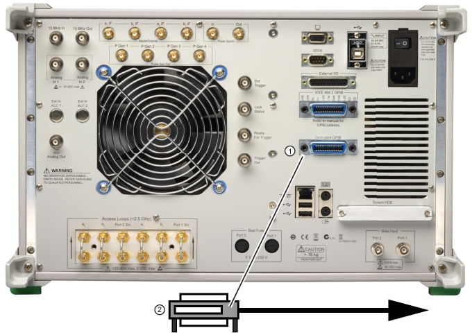
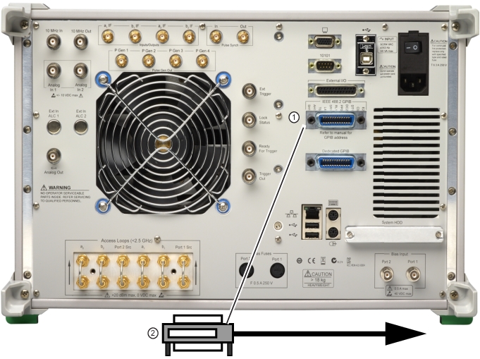
1. Connect GPIB devices to the VNA rear panel Dedicated GPIB Port using the appropriate length GPIB cable.
VectorStar MS464xB Series VNA Dedicated GPIB Port
1. Rear Panel Dedicated GPIB Port for control of connected external sources, power meters, and frequency counters.
2. GPIB Cable Connection to peripheral devices.
2. Power-up the VectorStar MS464xB Series VNA and any attached GPIB devices, and allow the system to warm up for at least 90 minutes.
3. Navigate to the REMOTE INTER menu:
• MAIN | System | SYSTEM | Remote Interface | REMOTE INTER.
• A detailed menu description is located in the User Interface Reference Manual.
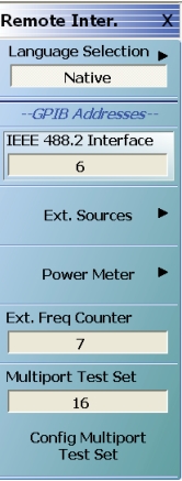
REMOTE INTER (REMOTE INTERFACE) Menu
On the REMOTE INTER. (REMOTE INTERFACE) menu:
The IEEE 488.2 Interface, Ext. Sources, Ext. Power Meter, Ext. Freq Counter, and the Multiport Test Set buttons control GPIB addresses for the subject devices.
The Ext. Sources button displays the EXT. SRC. ADDR. menu where GPIB addresses are assigned for external source 1 through external source 4.
The Power Meter button displays the POWER METERS menu where GPIB addresses are assigned for External, W-Band, and D-Band power meters source.
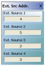
4. The GPIB address for any controlled device can be kept at the factory default values or changed as required. The default GPIB addresses are:
• External Source 1 = 4
• External Source 2 = 5
• External Source 3 = 2
• External Source 4 = 3
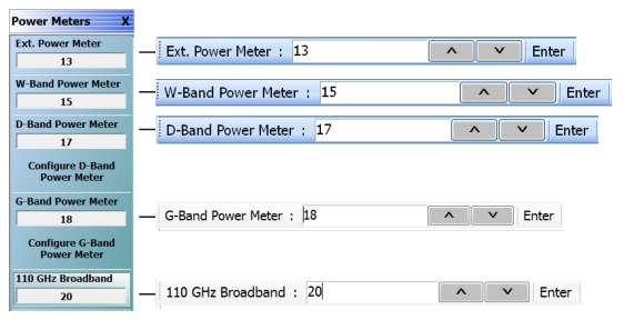
• Power Meter (External) = 13
• Power Meter (W-Band) = 15
• Power Meter (D-Band) = 17
• Power Meter (G-Band) = 18
• Power Meter (110 GHz broadband) = 20
• Frequency Counter = 7
• Multiport Test Set = 16
• Only available when a MN4694C or MN4797C Multiport/4-Port Test Set is installed.
• The test set must be on and the VNA must be rebooted for any GPIB address change to take effect.
• See the VectorStar MN469xC Multiport Test Set Installation Guide for complete installation and configuration instructions.
• MAIN | System | SYSTEM | Remote Interface | REMOTE INTER. | Ext. Sources | EXT. SRC. ADDR
• A detailed description of the menu is available in the User Interface Reference Manual.
EXT. SRC. ADDR. (EXTERNAL SOURCE ADDRESS) Menu
6. If a change of GPIB address is required, click the device button, and the device field toolbar appears as shown below:
7. Use the front panel keys, a keyboard, or mouse to set the required GPIB address.
8. Click the Enter button to set the new GPIB address.
For information on the programming command sets, refer to the VectorStar MS464xB Series VNAProgramming Manual.
9. The GPIB addresses for Power Meters are changed on the POWER METERS sub-menu shown below in Figure: Power Meters Menu.
• MAIN | System | SYSTEM | Remote Interface | REMOTE INTER. | Power Meter | POWER METERS.
Power Meters Menu
Configuring the IEEE 488.2 GPIB Port
Use this procedure to set up the talker/listener port to control the VNA remotely over an IEEE 488.2 GPIB bus network. In this configuration, an external computer/controller is physically connected to the VNA rear panel IEEE 488.2 GPIB Port with a standard GPIB cable. Most of the VectorStar MS464xB Series VNA functions (except power on/off and initialization of the internal drive) can be controlled remotely by an external computer/controller via the IEEE-488.2 GPIB bus network.
1. Connect the VNA to the GPIB Controller using the rear panel IEEE 488.2 GPIB Port DB-24 (f) connector and a standard GPIB cable.
IEEE 488.2 GPIB Talker/Listener Ports
1. 1. IEEE 488.2 (Upper) Port
2. GPIB Cable Connection. Note that the Dedicated GPIB Port is not used in this configuration.
2. Apply power to the VectorStar MS464xB Series VNA and allow the system to warm up for at least 90 minutes.
3. Once the software has finished loading and start-up testing is complete, the instrument is ready to be remotely controlled via the GPIB. The instrument will not respond to GPIB commands until the instrument’s software has been loaded.
Note
The factory default GPIB address for the instrument is six (6).
Configuring the VectorStar VNA GPIB Address
To change the VectorStar VNA GPIB address:
1. Navigate to the REMOTE INTER. menu:
• MAIN | System | SYSTEM | Remote Interface | REMOTE INTER.
2. On the REMOTE INTER menu, the IEEE 488.2 GPIB button.
The IEEE 488.2 GPIB toolbar appears below the icon toolbar near the top of the display.
3. Use the front panel keys, a keyboard, or a mouse to set the required GPIB address.
4. Click the Enter button to set the new GPIB address.
For information on the programming command sets, refer to the:
• VectorStar MS464xB Series VNA Programming Manual
• VectorStar MS464xB Series VNA Programming Manual Supplement