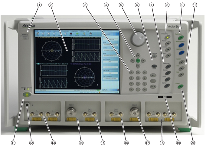
Front Panel Hard Keys and Functions (7 of 8)
Key Name | Primary Functions |
|---|
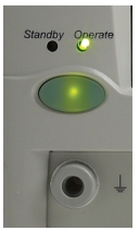
Power Key and Chassis Ground Connector
|
Standby/Operate Key | Pressing and holding the Standby/Operate key for at least one (1) second toggles the VNA between operate mode and standby mode. Power Up To power up the VNA into Standby mode, connect the instrument to AC power and then set the rear panel AC Power Rocker Switch (which is part of the upper right corner AC Power Input Module) to “|” or ON. The orange Standby LED on the front panel is illuminated and the Standby/Operate key is illuminated with an orange LED. Standby to Operate Mode With the VNA in standby mode, to change to operate mode, press and hold the Standby/Operate key for at least one (1) second. The green Operate LED is illuminated and the Standby/Operate key is illuminated with a green LED. Operate to Standby Mode With the VNA in operate mode, to change to standby mode, press and hold the Standby/Operate key for at least one (1) second. The orange Standby LED is illuminated and the Standby/Operate key is illuminated with an orange LED. Power Off With the VNA in standby mode, to remove AC power from the VNA and turn the VNA off, set the rear panel AC Power Rocker Switch to “O” or OFF. Do not remove AC Power from the VNA while it is in operate mode. Do not turn off the VNA while it is in operate mode. |
Chassis Grounding Port | Provides an instrument chassis and signal grounding (earth) point. Banana (f). |
Calibration, Measurement, and Application Keys 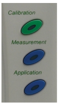 |
Calibration Key | Pressing Calibration displays the user interface CALIBRATION menu. • MAIN | Calibration | CALIBRATION |
Measurement Key | Pressing Measurement displays the MEASUREMENT menu in the user interface display. • MAIN | Measurement | MEASUREMENT |
Application Key | Pressing Application displays the APPLICATION menu in the user interface display. • MAIN | Application | APPLICATION |
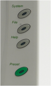
System, File, Help, and Preset Keys |
System Key | Pressing System displays the System menu in the user interface display. • MAIN | System | SYSTEM |
File Key | Pressing File displays the File menu in the user interface display. • MAIN | File | FILE |
Help Key | Pressing Help displays the Help menu in the user interface display. • MENU BAR | Help | Context Sensitive Help |
Preset Key | Returns the instrument (or presets it) to the last active configuration preset loaded as defined and set in the PRESET SETUP menu. Depending on the user-set preset configuration, this can be either: • User Defined: A previously saved user-defined state. • Default: The factory as-shipped state. • Default 0: The factory original setting. The user selects which preset mode is used. • MENU BAR | Utilities | Preset • MAIN | System | SYSTEM | Setup | SETUP | Preset Setup | PRESET SETUP |
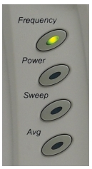
Frequency, Power, and Sweep Setup Key Group
|
Frequency Key | Pressing Frequency displays the FREQUENCY menu in the user interface display. • MAIN | Frequency | FREQUENCY |
Power Key | Pressing Power displays the POWER menu in the user interface display. • MAIN | Power | POWER |
Sweep Key | Pressing Sweep displays the SWEEP menu in the user interface display. • MAIN | Sweep Setup | SWEEP SETUP |
Average Key | Pressing Avg displays the AVERAGING menu in the user interface display. • MAIN | Averaging | AVERAGING |
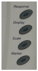
Response, Display, Scale, and Marker Key Group
|
Response Key | Pressing Response displays the Response menu in the user interface display. The RESPONSE menu displayed depends on whether the instrument is in 2-Port or 4-Port mode. • MAIN | Response | RESPONSE |
Display Key | Pressing Display displays the Display menu in the user interface display. • MAIN | Display | DISPLAY |
Scale Key | Pressing Scale displays the Scale menu in the user interface display. • MAIN | Scale | SCALE menu |
Marker Key | Pressing Marker displays the Marker menu in the user interface display. • MAIN | Marker | MARKERS [1] |
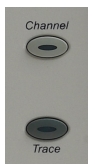
Channel and Trace Key Group
|
Channel Key | Pressing Channel displays the Channel menu in the user interface display. • MAIN | Channel | CHANNEL |
Trace Key | Pressing Trace displays the Trace menu in the user interface display. • MAIN | Trace | TRACE |
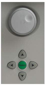
Navigation and Data Entry Keys
|
Rotary Knob | The operation of the Rotary Knob varies depending on the cursor focus. On selections, rotating the Rotary Knob clockwise moves the selection down. Rotating counterclockwise moves the selection up. On menus, moves the button focus up or down. On field toolbars, increases or decreases the field value. Pressing the Rotary Knob starts the action of the selected menu button or applies the input value of the selected field toolbar. |
Up Arrow Key | Pressing Up moves the cursor or selection up. |
Down Arrow Key | Pressing Down moves the cursor or selection down. |
Left Arrow Key | Pressing Left moves the cursor or selection to the left. |
Right Arrow Key | Pressing Right moves the cursor or selection to the right. |
Select Key | Pressing Select starts the action of the selected menu button.
Same as pressing the Rotary Knob. |
Keypad and Data Entry Key Group 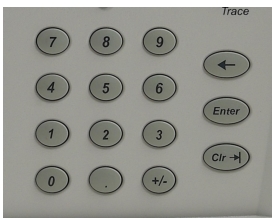 |
Keypad Digit Keys | Used to enter digits from 0 (zero) to 9 (nine). |
. (Decimal) Key | Used to enter a decimal point. |
+/- (Plus/Minus) Key | Toggles an entered value between + (plus) and – (minus). |
Backspace / Delete Key | Deletes characters and moves the cursor to the left. |
Enter Key | Causes the user-defined value or the field toolbar value to be entered into the instrument. |
Clear/Tab Key | Clears the value of a field or tabs forward to the next field. |
Test Port 1 and Loop Connectors 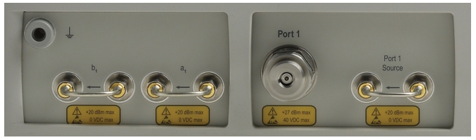 |
Test Port 1 | Universal Test Port Connector • K (m) for MS4642B and MS4644B • V (m) for MS4645B and MS4647B • Damage Input Levels: +27 dBm max, 40 VDC max • Exchangeable in case of damage. |
Port 1 Source | Source paths, ≥ 2.5 GHz coverage. • K (f) for MS4642B and MS4644B. • V (f) for MS4645B and MS4647B. • Damage Input Levels: +20 dBm max, 0 VDC max • Optional. Included with Option 51 and 6x. This port is also used to interface with MN469xx Series 4-Port Test Sets and ME7838x Series 4-Port Broadband/Millimeter Wave Systems. |
b1 Test Receiver - Port 1 | Test receiver paths. • As above. • Optional. Included with Option 51 and 6x. |
a1 Reference Receiver - Port 1 | Reference receiver paths. • As above. • Optional. Included with Option 51 and 6x. |
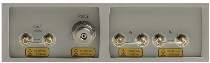
Test Port 2 and Loop Connectors
|
Test Port 2 | Universal Test Port Connector. • K (m) for MS4642B and MS4644B • V (m) for MS4645B and MS4647B • Damage Input Levels: +27 dBm max, 40 VDC max • Exchangeable in case of damage. |
Port 2 Source | Source paths, ≥ 2.5 GHz coverage. • K (f) connectors for the MS4642B and MS4644B VNAs. • V (f) connectors for the MS4645B and MS4647B VNAs. • Damage Input Levels: +20 dBm max, 0 VDC max • Optional. Included with Option 51 and 6x. This port is also used to interface with MN469xx Series 4-Port Test Sets and ME7838x 4-Port Series Broadband/Millimeter Wave Systems. |
b2 Test Receiver - Port 2 | Test receiver paths. • As above. • Optional. Included with Option 51 and 6x. |
a2 Reference Receiver - Port 2 | Reference receiver paths. • As above. • Optional. Included with Option 51 and 6x. |
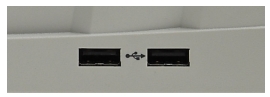
Front Panel USB Ports
|
USB Ports | USB 2.0 Type A Ports, two (2) each. • For peripherals such as keyboard, mouse, memory stick, or hardware key. • There are two additional USB 2.0 Type A Ports located on the rear panel. |