The Icon Toolbar is located immediately below the Menu Bar and allows single-click access to over 31 menus and functions. The icon toolbar is user-configurable and up to 10 icons be displayed at in any configuration.
The available icon functions that can be added to a user-defined icon toolbar are listed in table below. Once configured, a preset save allows the toolbar configuration to be recalled at any time.
The procedures for changing the icon toolbar are described following the icon table and uses the CUSTOMIZE (ICON) TOOLBAR Dialog Box below. When a user-defined toolbar is configured, the first selected icon goes to the left-most position on the toolbar. The tenth selected icon goes to the right-most position on the toolbar.
Icon Descriptions - Listed Alphabetically (1 of 6)
Icon Name
Icon
Description
Icon Description Definitions
Default Icons – These are one of the 10 default icons and are provided after a return to the factory standard configuration. Front Panel Key – If available, the front panel hard key that accesses this menu or function. Keyboard – If available, the keyboard shortcut to access this menu or function. Menu Bar – If available, navigation path to access this menu or function. Navigation – To navigate to this menu or function from the MAIN menu. Description – If available, where this menu, dialog box, or function is described in greater detail in this document.
Application Icon
Select displays the right-side APPLICATION menu.
• Front Panel Key: Application
• Keyboard: ALT + 6
• Menu Bar: MENU BAR | 6 Application | 6 APPLICATION
• MAIN | Application | APPLICATION
Average Icon
Select displays the right-side AVERAGING menu.
• Front Panel Key: Avg (Average)
• Keyboard: ALT + 2, then 4
• MENU BAR | Channel | Averaging
• MAIN | Averaging | AVERAGING
Calibration Icon
Default Icon. Select displays the right-side CALIBRATION menu.
• Front Panel Key: Calibration
• Keyboard: ALT + 4
• MENU BAR | Calibration
• MAIN | Calibration | CALIBRATION
Ch->Max Icon
When multiple channels are used, select activates and displays the channel with the maximum trace value.
• MAIN | Channel | CHANNEL | Chan. Max
Ch->Next Icon
When multiple channels are used, select activates and displays the next higher channel number. If the highest channel number is currently active, channel 1 (one) is activated and displayed.
• MAIN | Channel | CHANNEL | Chan. Next
Ch->Prev Icon
When multiple channels are used, select activates and displays the next lower channel number. If channel 1 (one) is currently active, the highest numbered channel is activated and displayed.
• MAIN | Channel | CHANNEL | Chan. Previous
Channel Icon
Default Icon. Select displays the right-side CHANNEL menu.
• Front Panel Key: Channel
• Keyboard: ALT + 2
• MENU BAR | Channel | Channel Menu
• MAIN | Channel | CHANNEL
Continue Icon
After a system pause or hold with the Hold icon, the Continue icon resumes operation with all prior settings in effect.
• MAIN | Sweep Setup | SWEEP SETUP | Hold Functions | HOLD FUNCTIONS | Continue
Custom Icon 1
Select performs the action defined for Custom Icon 1 using the right-side context menu. After definition, custom-action icons are displayed in the Icon Bar.
The steps to define a Custom-action Icon are described in the VectorStar MS464xB Series Microwave Vector Network Analyzer User Interface and Reference Manual (10410-00319).
Custom Icon 2
Select performs the action defined for Custom Icon 2 using the right-side context menu. After definition, custom-action icons are displayed in the Icon Bar.
The steps to define a Custom-action Icon are described in the VectorStar MS464xB Series Microwave Vector Network Analyzer User Interface and Reference Manual (10410-00319).
Custom Icon 3
Select performs the action defined for Custom Icon 3 using the right-side context menu. After definition, custom-action icons are displayed in the Icon Bar.
The steps to define a Custom-action Icon are described in the VectorStar MS464xB Series Microwave Vector Network Analyzer User Interface and Reference Manual (10410-00319).
Custom Icon 4
Select performs the action defined for Custom Icon 4 using the right-side context menu. After definition, custom-action icons are displayed in the Icon Bar.
The steps to define a Custom-action Icon are described in the VectorStar MS464xB Series Microwave Vector Network Analyzer User Interface and Reference Manual (10410-00319).
Custom Icon 5
Select performs the action defined for Custom Icon 5 using the right-side context menu. After definition, custom-action icons are displayed in the Icon Bar.
The steps to define a Custom-action Icon are described in the VectorStar MS464xB Series Microwave Vector Network Analyzer User Interface and Reference Manual (10410-00319).
Display Icon
Default Icon. Select displays the right-side DISPLAY menu.
• Front Panel Key: Display
• Keyboard: ALT + 3, then 2
• MENU BAR | Trace | Display
• MAIN | Trace | TRACE
File Icon
Select displays the right-side FILE menu.
• Front Panel Key: File
• Keyboard: ALT + 1
• MAIN | File | FILE
Freq Icon
Default Icon. Select displays the right-side FREQUENCY menu.
• Front Panel Key: Frequency
• Keyboard: ALT + 2 then 1
• MENU BAR | Channel | Frequency
• MAIN | Frequency | FREQUENCY
Help Icon
Select displays the context-sensitive HELP system for the current instrument menu display. Click OK to clear.
• Front Panel Key: Help
• Keyboard: – ALT + 8, then 1 – ALT + 8, then 2
• MENU BAR | Help | Context Sensitive Help
Hold Icon
Select pauses the system operation, retaining all system presets and current configuration settings.
• MAIN | Sweep Setup | SWEEP SETUP | Hold Functions | HOLD FUNCTIONS | Hold
Marker->Max Icon
Displays marker with maximum value.
• MAIN | Marker | MARKER [1] | Marker Search | MARKER SEARCH | Max
Marker->Min Icon
Select displays the marker with minimum value.
• MAIN | Marker | MARKER [1] | Marker Search | MARKER SEARCH | Min
Marker->Off Icon
Select turns all marker displays off.
• MAIN | Marker | MARKER [1] | Marker Setup | MARKER SETUP | All Markers Off
Marker->Peak Icon
Select displays marker with the highest peak value.
Select displays the next peak value marker to the left of current selected marker.
• MAIN | Marker | MARKER [1] | Marker Search | MARKER SEARCH | Peak | PEAK | Search Left
Marker->Pk Rt Icon
Select moves the current active marker to the next trace peak value to the right of its current position.
• MAIN | Marker | MARKER [1] | Marker Search | MARKER SEARCH | Peak | PEAK | Search Right
Marker Icon
Default Icon. Select displays the right-side MARKERS [1] menu.
• Front Panel Key: Marker
• Keyboard: ALT + 3, then 4
• MENU BAR | Trace | Marker
• MAIN | Marker | MARKER [1]
Measurement Icon
Select displays the right-side MEASUREMENT menu.
• Front Panel Key: Measurement
• Keyboard: ALT + 5
• MENU BAR | Measurement | 5 MESUREMENT
• MAIN | Measurement
Power Icon
Default Icon. Select displays the right-side POWER menu.
• Front Panel Key: Power
• Keyboard Equivalent: ALT + 2, then 2
• MENU BAR | Channel | Power
• MAIN | Power | POWER
Preset Icon
Default Icon. Select returns the system to its prior preset status which is the status at the time of the last preset save.
• Front Panel Key: Preset
• Keyboard: ALT + 7, then 5
• MENU BAR | Utilities | Preset
The instrument preset function is only available from the MENU BAR and the instrument front panel key. To setup the preset function, use the PRESET SETUP menu described at the locations below:
• MAIN | System | SYSTEM | Preset Setup | PRESET SETUP
Print Icon
Select displays the PRINT dialog box, usually to print a copy of the main display. Once the dialog box appears, click OK to print; click Cancel to abort.
• MENU BAR | File | Print
• MAIN | File | FILE | Print | PRINT Dialog Box
Response Icon
Default Icon. Select displays the right-side RESPONSE menu.
• Front Panel Key: Response
• Keyboard: ALT + 3, then 1
• MENU BAR | Trace | Response
• MAIN | Response | RESPONSE
Scale Icon
Default Icon. Select displays the right-side SCALE menu.
• Front Panel Key: Scale
• Keyboard: ALT + 3, then 3
• MENU BAR | Trace | Scale
• Main | Scale | SCALE
Sweep Icon
Select displays the right-side SWEEP SETUP menu.
• Front Panel Key: Sweep
• Keyboard: ALT + 2, then 2
• MENU BAR | Channel | Sweep
• MAIN | Sweep | SWEEP
System Icon
Select displays the right-side SYSTEM menu.
• Front Panel Key: System
• Keyboard: ALT + 7, then 1
• MENU BAR | Utilities | System
• MAIN | System | SYSTEM
Tr->Max Icon
Select maximizes the display with the currently active trace.
• Keyboard: ALT + 3, then 6
• MENU BAR | Trace | Trace Max
• MAIN | Trace | TRACE | Trace Max
Tr->Next Icon
Select displays the next higher trace number. When the highest trace number is reached, the next click displays trace number 1 (one).
• Keyboard: ALT + 3, then 8
• MENU BAR | Trace | Trace Next
• MAIN | Trace | TRACE | Trace Next
Tr->Previous Icon
Select displays the next lower trace number. When the lowest trace number 1 is reached, the next click displays the highest numbered trace.
• Keyboard: ALT + 3 then 7
• MENU BAR | Trace | Trace Prev.
• MAIN | Trace | TRACE | Trace Previous
Trace Icon
Default Icon. Select displays the right-sideTRACE menu.
• Front Panel Key: Trace
• Keyboard: ALT + 3, then 5
• MENU BAR | Trace | Trace Menu
• MAIN | Trace | TRACE
CUSTOMIZE (ICON) TOOLBAR Dialog Box
Use the CUSTOMIZE TOOLBAR dialog box to setup the Icon Toolbar with the icons you need for quick access to commands and functions. Once configured, and after a Preset Configuration save, the Icon Toolbar settings can be recalled with the other preset configuration parameters.
• MENU BAR | Utilities | Customize Toolbar | CUSTOMIZE TOOLBAR Dialog Box
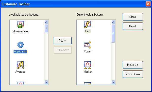
CUSTOMIZE TOOLBAR Dialog Box
Procedure
With the CUSTOMIZE TOOLBAR dialog box open, the left-side Available Toolbar Buttons area shows icons that are not in use on the current toolbar, while the right-side Current Toolbar Buttons area shows the current in-use icons.
Removing Icons
1. To change the icons in the current icon toolbar, in the right side Current button area, select an icon to remove. When selected, the Add-> and <-Remove buttons become available.
2. Remove unwanted icons as required by selecting the icon and then clicking the <-Remove button.
3. Removed icons appear at the bottom of the Available Toolbar Buttons list.
Adding Icons
1. Scroll through the Available Toolbar Buttons list and select an icon to add, then click the Add-> button. The selected icon appears in the right side Current Toolbar Buttons area.
2. Repeat the selection process until all required icons listed in the right side Current Toolbar Buttons area or you have reached the maximum of 10 icons.
3. In the Current Toolbar Button display, the icon displayed at the top of the list will appear on the extreme list of the toolbar. The tenth icon displayed at the bottom of the list will appear on the extreme right of the toolbar.
Moving Icons
To change the left to right sequence of the current icons, select an icon, and click the Move Up/Move Down buttons until the icons are correctly positioned left to right.
Saving the Configuration
When the icons are in the correct sequence. Click the Close button to apply the icons to the icon toolbar. It is recommended that a Preset Save be preformed to save the icon toolbar configuration. If the icon toolbar needs adjustment, re-open the Customize Toolbar dialog box and repeat the steps above.
Reset to Factory Default
To return the icon toolbar to its factory default state, click the Reset button.