Remote Spectrum Monitors : MS27102A Installation : Instrument Overview
 
Instrument Overview
This section provides a brief overview of the instrument and the supplied accessories.
The MS27102A instrument consists of the following main components:
MS27102A Remote Spectrum Monitor
Mounting brackets and fasteners
IP67 Ethernet and power connector glands
Indoor power supply and power cable with assembled connector gland
GPS antenna
Connectors and Chassis
MS27102A Overview
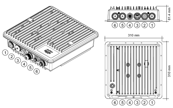
1. GPS Antenna, SMA(f)
2. No Connection
3. 3-pin Power Input (see Power Supply Gland Assembly)
4. Ethernet (see Ethernet Gland Assembly)
5. RF Input Port 2, N(f) (optional)
6. RF Input Port 1, N(f)
Mounting Hardware
MS27102A Mounting Hardware
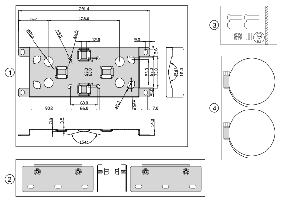
1. Universal mounting bracket detail
2. Mounting bracket extensions and nuts (6 mm hex nuts, 2 each, used for wall mounting only)
3. Stainless machine screw set (10 mm M6 x 0.8, 4 each)
4. Stainless strap clamps (101 mm maximum diameter, 2 each)
Connector Glands
The figure below illustrates the IP67 rated Ethernet (top) and power connector (bottom) gland assemblies.
Ethernet and Power Connector Gland Assemblies
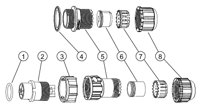
1. O-ring
2. Housing with connector pins
3. Lock nut
4. Gasket
5. Connector body
6. Seals
7. Inner collet clip
8. Sealing nut
Power Supply
The MS27102A Remote Spectrum Monitor comes with an indoor AC/DC power converter with a pre-assembled power cable and gland. This is to be used only for indoor applications. For outdoor usage, a DC power supply must be supplied by the user and must meet the following criteria:
Voltage rating: 11 VDC to 24 VDC (supplied at instrument connector)
Power dissipation: 11 W
Environmental ratings: IP67 rating recommended or otherwise suitable outdoor supply, including supply cabling
Power cabling: appropriate weather resistant cabling with adequately sized conductors for the length of run and power demand. The provided connector has screw terminals and will work for wire sizes from 14 AWG to 18 AWG with an outside cable diameter of 5.5 mm to 8.0 mm (0.22 to 0.31 in).