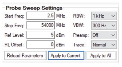
Type in the Start Frequency for live sweeps. Range is 9 kHz to maximum range of measuring instrument up to 54 GHz.
Frequency Stop
Type or enter the Stop Frequency for live sweeps. Range is 9 kHz to maximum range of measuring instrument up to 54 GHz.
Ref Level
Reference level for live sweeps.
RL Offset
Reference level offset for live sweeps.
RBW
Set Resolution Bandwidth (RBW) for live sweeps. Pull-down provides RBW of 1 Hz, 3 Hz, 10 Hz, 30 Hz, 100 Hz, 300 Hz, 1 kHz, 3 kHz, 10 kHz, 30 kHz, 100 kHz, 300 kHz, 1 MHz, and 3 MHz.
VBW
Set Video Bandwidth (VBW) for live sweeps. Pull-down provides RBW of 1 Hz, 3 Hz, 10 Hz, 30 Hz, 100 Hz, 300 Hz, 1 kHz, 3 kHz, 10 kHz, 30 kHz, 100 kHz, 300 kHz, 1 MHz, and 3 MHz.
Preamp
Toggle Preamp state (On/Off).
Trace
Select the desired Trace Mode Setting.
• Normal: Displays data for the current trace sweep. Can be applied to several channel probes in the database.
• Rolling Min Hold: Minimum value at each frequency point over the last trace sweeps. Can be applied to several channel probes in the database.
• Rolling Max Hold: Maximum value at each frequency point over the last trace sweeps. Can be applied to one channel probe in the database.
• Average: Average value at each frequency point over the last trace sweeps. Can be applied to only one channel probe in the database.
• Min Hold: Minimum value at each frequency point over the last trace sweep. Can be applied to only one channel probe in the database.
• Max Hold: Maximum value at each frequency point over the last trace sweep. Can be applied to only one channel probe in the database.
Reset Parameters
Reset target receiver Sweep Parameters from database.
Apply to Current
Apply the current settings above to the selected target receiver.
Apply to All
Apply the current settings above to all target receivers.
Active Button Viewer
Refer to Figure: Location Finder Utilities. The Active Icon View displays the corresponding active buttons from the Settings and Control panels. Inactive Icons will be grayed. These active icons provide a visual tool of the settings and control buttons that are in use. Note that the icons in this panel are not activated from this location, but must be selected via the Settings and Control panel buttons to execute.