Click to toggle the Start/Stop button to stop the simulator Source 1 and Source 2 activity. Click the power label will sweep each target receiver frequency indicated in the Interferer 1 Configuration. The power of the interferer 1 frequency is then displayed for each target receiver. Toggle the Start/Stop Button to Start will initiate the sweep again.
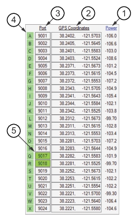
GPS Coordinates Column
This column lists the GPS coordinates of the Remote Spectrum Monitor listed in the Port Column.
Port Column
This column lists the target receiver ports. Maximum number that can be added to the list is 24. Click on the Port number for one of the simulators and note that the background color changes color. This marks it as Busy.
Slot ID
The probes are named A-X with green labels along the left edge. Click a label and the label changes color. This deactivates the probe. Click again to reactivate the probe in the simulator.
Busy State
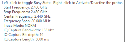
Left click a target receiver activates a busy status flag. When it is set, the target receiver shows ‘BUSY’ prominently on the Web GUI. This is a User setting that can be used or ignored. Right-Click to Activate/Deactivate the probe – This setting will turn off the target receiver or toggle to turn back on. Position the mouse pointer over a port will display the probes configuration as shown below.
Target Receiver Communication
Target receiver probes normally communicate on Ethernet port 9001. This is the port that the simulator uses by default. You can only have one program using a port at a time on a single PC, so we set each simulator to use a different port, 9001 through 9024.
Simulator Entries
Below the tool-bar is a list of simulators. Click the Source check box to activate a simulator. Uncheck the check box to deactivate the simulator. Simulator Control supports twenty-four simulators.
GPS Coordinates
Next to each port number are the GPS coordinates that each simulator will respond with. You can copy and paste numeric values into these boxes, or edit with the keyboard. You can also place the mouse over the GPS coordinates and the roll the mouse wheel up and down to shift the Latitude North or South. Use Ctrl-mouse wheel to shift east and west.