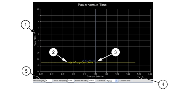
PowerXpert™ Help : Using Power Master with PowerXpert : Graticule Settings and Graphical Display Area
 
Graticule Settings and Graphical Display Area
This section provides a brief overview of the graticule settings and graphical display areas that are presented in the different operating modes of PowerXpert. The Power versus Time graph is used in all modes and provides the ability to plot measured power with respect to time (or time slots). This feature can be used for drift testing, tuning circuits, and for monitoring circuit behaviors to external stimuli. The graph starts automatically and updates continuously in real time.
The following Power versus Time graph is used in Continuous Mode:
PowerXpert Graphical Display Area (Continuous Average Mode)
Index
Description
1
The vertical scale displays the power level in dBm, regardless of the Units settings of dBm, μW, mW, or W from the Continuous Mode settings area.
2
Graphical trace display showing the power level as a function of time.
3
Marker showing as a vertical blue line with an x on the marker point and numerical values for the time (in minutes) and power level (in dBm). The marker is available for reading power at an instant of time. It can be dragged with the mouse and can be centered in the display via the Center marker button.
4
The horizontal scale displays the time in minutes and may be increased or decreased from the graticule settings area. This scale increases up to a maximum of 1440 minutes.
5
Graticule settings area:
Time Span (min): Sets the current time span setting from 0.1 minutes up to a maximum of 1440 minutes.
Power Max (dBm): Sets the upper power level for the vertical scale.
Power Min (dBm): Sets the lower power level for the vertical scale.
Power Max (dBm) and Power Min (dBm) settings are not available when set to Automatic.
Scale Mode: Sets the vertical scaling to Automatic or Manual.
Zero Sensor
Zeroing is not necessary for the MA245xxA Power Master. When selecting Multiple Analyzer Display, see Multiple Sensor Display from the Tools menu, Tools Menu it will be necessary to Zero the MA24208A, MA24218A, MA24330A, MA24340A, and the MA24350A USB power sensors before making measurements.
Averages
The Averages setting allows you to specify the number of measurements that are averaged to calculate the displayed power. A setting of 1 disables averaging.
Offset
A fixed value (in dB) specified by the user is applied as a power offset to the sensor. A positive offset adds a value to the power readings and can be used to compensate for attenuators, couplers, limiters, and other lossy devices. A negative value subtracts a value from the power reading and can be used to compensate for amplification in the measurement path.
Apply Above Settings Button
The Apply Above Settings button applies all changes made to the settings. Changes to these settings do not take affect until clicking this button.