The frequency response of the Power Master is tested at one low power level against a reference power sensor or Power Master of known measurement uncertainty. The reference power sensor or Power Master should be calibrated by a reputable standards laboratory using instruments with low published measurement uncertainty values. To perform the comparison, both power sensors or Power Masters are used to measure the output power of a synthesizer with a high quality attenuator at the output. The attenuator improves the source match of the synthesizer by lowering the mismatch ripples, thereby lowering the uncertainty in the comparison.
6. Repeat Steps 3 through 6 until all frequencies are measured.
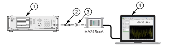
7. Turn Off RF output. Disconnect the reference sensor and connect MA245xxA Power Master to the attenuator.
8. Set synthesizer frequency to 50 MHz CW. Turn On RF output.
9. Set to Continuous Mode: Mode = Channel power, Span = 1MHz, Units =dBm, Range = Upper, Averages = 64
10. Enter test frequency in GHz on PowerXpert.
11. Record the power indicated by the MA245xxA Power Master.
12. Set synthesizer frequency to the next frequency.
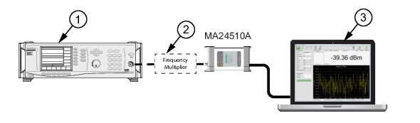
• Note: The frequency multiplier doubles the frequency, so the synthesizer frequency must be set to 1/2 the test frequency with the 71 to 110 GHz setup.
13. Repeat Steps 10 through 13 until all frequencies are measured.
14. Calculate the absolute difference between the Reference power and MA245xxA Power Master measurement.
15. Compare the power difference to the maximum allowed difference specified. If the difference exceeds the maximum allowed difference, contact Anritsu Customer Service.
MA245xxA Power Master Test Measurement Results
Frequency (GHz)
A
Reference Power Measurement (dBm)
B
MA245xxA Measurement (dBm)
|A-B|
Absolute Value of Difference in Power Measurements (dB)