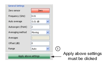
The General Settings settings shown in Figure: General Settings are common to all four modes and power sensors.
General Settings
Index
Description
1
Button must be clicked to apply above settings
Zero Sensor
Zero the sensor before making power measurements. If frequent low-level measurements are being made, check the sensor zeroing often. Before zeroing the sensor, connect it to the DUT (device under test) test port and reduce RF power from the connection to a level 20 dB below the noise floor of the power sensor.
For the MA24105A power sensor, this level is less than –20 dBm. For the MA24106A power sensor, this level is less than –60 dBm. For the MA243x1A, this level is –67 dBm. For the MA24108A, MA24118A, MA24126A, and MA243x0A this level is less than –70 dBm. For the MA24208A, and MA24218A, this level is less than –70 dBm.
Leave the sensor connected to the DUT test port so that ground noise and thermal EMF (electro-magnetic fields) are zeroed out of the measurement. The sensor may also be connected to a grounded connector on the DUT or disconnected from any signal source.
Frequency
Entering the frequency of measurement applies frequency correction to the measured power. The power sensor has an internal EEPROM containing frequency calibration factors that were programmed into the sensor at the factory. The power sensor has an internal temperature sensor that reports its readings periodically to the microprocessor. The sensor makes all of the required calculations on the measurement once entering the measurement frequency.
Auto Average
Auto average is only available with the MA24x08A, MA24x18A, MA24126A and MA243x0A power sensors. Auto average sets the auto averaging status and count. When an auto averaging resolution is selected, the sensor chooses an averaging number that is a compromise between stabilizing the power reading and providing reasonable settling time. It does this by choosing an averaging number based on the power level currently being measured.
For most power levels, selecting auto averaging results in the power reading fluctuating by no more than twice the selected auto average resolution setting. However, near the low end of the measurement range, the power reading may fluctuate by more than this as the averaging number has been limited to maintain reasonable settling response time. Auto averaging only stabilizes the readings due to noise contributed by the power sensor electronics. Power variations that are the result of measuring modulated signals are not taken into account by the sensor in auto averaging. Setting Auto average to Off enables manual averaging.
Auto Averaging Source
Auto averaging source is only available in Scope Mode (to specify which point to use) and in Time Slot Mode (to specify which slot number to use). Auto averaging source is only available with the MA24x08A, MA24x18A, MA24126A and MA243x0A power sensors. Auto averaging source sets which display point or slot number to use for auto averaging. The auto averaging algorithm can only use one averaging number at a time and this point or slot number must be specified when Auto Average is enabled.
Averaging Method
Averaging method is only available with the MA24x08A, MA24x18A, MA24126A and MA243x0A power sensors. The types of averaging methods are Moving and Repeat.
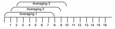
Moving: Averaging is continuously performed over the number of specified measurements. When the specified number is reached, the average is calculated. When the next measurement is finished the average is recalculated from the new start and end positions. Refer to the figure below that shows moving averaging performed over eight measurements.
Moving Averaging
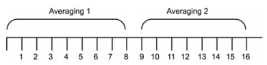
Repeat: Averaging is performed over the number of measurements specified. The displayed power is not updated until the next entire batch of measurements is complete. Refer to the figure below that shows repeat averaging performed over 8 measurements.
Repeat Averaging
Averages
The Averages setting allows you to specify the number of measurements that are averaged to calculate the displayed power. A setting of 1 disables averaging. This setting is only available when Auto Average is Off and applies equally to both forward and reverse measurements.
Offset
A fixed value (in dB) specified by the user is applied as a power offset to the sensor. A positive offset adds a value to the power readings and can be used to compensate for attenuators, couplers, limiters, and other lossy devices. A negative value subtracts a value from the power reading and can be used to compensate for amplification in the measurement path.
Range
Range allows the operating power range of the sensor to be set to the desired range. Setting to “Auto” means that sensor firmware determines the appropriate range for it to operate. Auto ranging is available only with MA24108A, MA24118A, MA24126A, MA24208A, MA24218A and MA243x0A power sensors.
Power Sensor Operating Power Range
<det range>
MA24105A
MA241xxA
MA242x8A
MA243x0A
0
Auto Range
Auto Range
Auto Range
Auto Range
1
Low power (+3 dBm to +38 dBm)
Channel A (+20 dBm to –7 dBm)
Channel A (+20 dBm to +4 dBm)
Channel A (+20 dBm to +4 dBm)
2
High power (+38 dBm to +51.76)
Channel B (<–7 dBm to –40 dBm)
Channel B (<+4 dBm to –16 dBm)
Channel B (+4 dBm to –16 dBm)
3
-
-
Chanel C (<–16 dBm to –60 dBm)
Chanel C (–16 dBm to –70 dBm)
In some instances, setting the range manually improves the measurement. For example, a low duty cycle, high crest factor signal, where average power may fall in one range and the peak power in another, may result in erroneous readings when the sensor is set to auto range. In this case, setting the range manually closer to the anticipated average power will increase the accuracy.
Apply Above Settings Button
The Apply above settings button applies all changes made to the Scope Mode settings. Changes to these settings do not take affect until clicking this button.