Trigger settings is only available in Time Slot Mode and Scope Mode with power sensor models MA24x08A, MA24x18A, and MA24126A. Trigger settings are available only in Scope mode with MA243x0A. Trigger is an event that initiates a measurement run. When the sensor is armed, it starts looking for the trigger. Once the trigger occurs, the sensor starts collecting data and measurement commences. Before arming the sensor, the sensor must be set up with the following trigger related parameters:
Trigger Settings
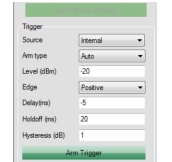
Trigger Source
• Internal Trigger: If internal trigger source is selected, the sensor triggers based on the signal level, edge/slope and noise immunity factor.
• External Trigger: When the sensor is setup with external trigger, it is triggered by the TTL/CMOS signal on the external trigger pin. In this trigger source, sensor can be set up to trigger at a particular edge of the TTL/CMOS signal. External trigger does not depend on any other trigger related parameter.
• Continuous Trigger: The sensor continuously collects data when the trigger source is set to continuous and does not look for any trigger event. Continuous trigger does not depend on any other trigger related parameters and these settings are unavailable for a Continuous trigger source.Trigger Arm Type
The trigger parameters are effective only if the sensor is armed. “Armed” is the state when the sensor is looking for a trigger. By default, the sensor is in Standby mode, it has to be armed before it starts looking for trigger. Trigger arming is effective only when the trigger source is set to internal or external. It does not play any role when the trigger source is continuous. An armed sensor returns the power automatically after a trigger has occurred and data has been collected and processed. The trigger can be armed in following ways:
• StandBy: This is the default arming state of the sensor. If the trigger source is internal or external, and the arm type is stand by, then the sensor will not make measurements or update the trace data. This is similar to the “stop” acquisition function of a digital oscilloscope. However, if the trigger source is continuous, then the sensor continuously collects and updates trace data.
• Auto Arm: In this state, the sensor rearms automatically after a trigger event has occurred and power is displayed. It is generally used to evaluate periodic waveforms. In other words, the sensor rearms after every measurement run. The power is displayed/updated automatically after every trigger event.
• Single Arm: The trigger is first armed and, once the trigger event occurs, the data is collected and the display updated, then the trigger is unarmed. Thus, only one measurement run and display update is performed. This mode is generally used to evaluate non-periodic waveforms. If averaging is selected, the results will not usually be very meaningful because all of the measurement runs commence with only the one trigger event and occur successively. The individual measurement runs are not synchronized to the input signal; therefore, averaging should not normally be used with the single arming type.
• Multiarm: Multiarming is used when averaging is needed, but continuous display updates are not needed. In this mode the trigger is armed, then once the trigger event occurs, the measurement data is taken and the display is updated (for the moving average method). Then the trigger is rearmed. This cycle repeats N times where N is the current averaging number. If the averaging method is Moving, then the display is updated after each trigger and measurement run. If the averaging method is Repeat, then the display is updated only after N triggers and measurement runs. Once N runs are complete, the trigger is unarmed.
Trigger Level
Sets the power level threshold of the waveform under test that, when crossed, triggers a measurement. It is used during internal triggering only.
Trigger Edge
It sets the trigger edge for internal and external trigger. Trigger edge can be set to positive or negative. For internal trigger, the sensor triggers only when the signal crosses the trigger level from high to low when set to negative edge; the sensor triggers only when the signal crosses the trigger level from low to high when set to positive. For external trigger, the sensor triggers when the TTL/CMOS signal on the external trigger pin falls from high to low when set to negative; the sensor triggers when the TTL/CMOS signal on the external trigger pin rises from low to high when set to positive.
Trigger Delay
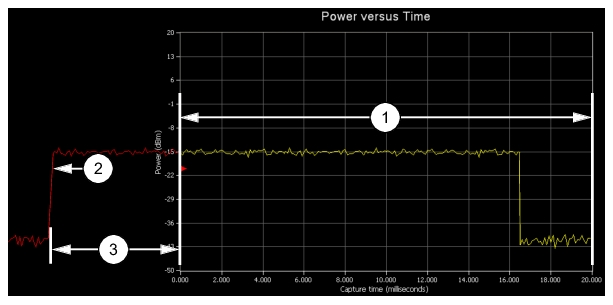
A trigger delay allows a time lag (positive or negative) between the trigger event and the data displayed on the screen. An example of Trigger Delay with positive parameters is shown in Figure: Trigger Delay Positive Parameters.
Specifying a positive delay has the effect of displaying data occurring some time after the trigger event. When the delay is positive, the sensor waits for the set delay time after a trigger before it starts taking readings. The sensor is unresponsive during the wait period and cannot be aborted. For example, for a capture time of 20 ms and a delay of 1 ms, the length of the capture would be from 1 ms to 21 ms given that the trigger occurs at time, t = 0. The capture time is unaffected by a positive trigger delay.
Trigger Delay Positive Parameters
Index
Description
1
Capture Time (ms)
2
Trigger Level (dBm) and Positive Edge Trigger
3
Positive Trigger Delay Time (ms)
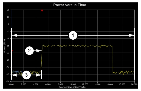
Specifying a negative delay allows the user to display data occurring immediately before the trigger event. An example of Trigger Delay with positive parameters is shown in Figure: Trigger Delay Negative Parameters. The negative delay cannot be greater than or equal to the capture time. If the capture time conflicts with the trigger delay, an error is generated.
Trigger Delay Negative Parameters
Index
Description
1
Capture Time (ms)
2
Trigger Level (dBm) and Positive Edge Trigger
3
Negative Trigger Delay Time (ms)
Trigger Holdoff
Trigger Holdoff is available only in MA242x8A and MA243x0A models during internal or external triggering. It is intended to prevent problems arising from multi-triggering by suppressing triggers for a time after the first detection. When detecting noisy RF pulses, hysteresis and noise immunity may not be sufficient for reliably detecting the correct trigger event. A noisy burst might always drop below the lower hysteresis threshold and be missed entirely. Similarly, a noisy burst may not cross the noise immunity threshold enough times to cause a trigger detection. With hysteresis and noise immunity off, a trigger hold off duration slightly greater than the signal burst time will ensure a stable trigger capture.
Noise Immunity
Noise Immunity is available only in MA24108A, MA24118A, and MA24126A models. This feature is available during internal triggering and is intended to minimize the risk of triggering on an unintended edge. For very noisy signals, the sensor can trigger at an undesired point or edge. To provide immunity against such situations, the sensor can be set to wait for N number of samples to cross the trigger level before it triggers. Higher values of N result in increased noise immunity, but also increase the trigger latency. It is advised to use a negative trigger delay when using noise immunity. The negative delay required to reduce the trigger latency is the product of N and the sample duration of the power sensor (see sensor specifications), which is approximately 7 µs for the MA24108A and MA24118A. The default value for the trigger noise immunity factor is 1 (no immunity).
Hysteresis
Hysteresis is available in the MA242x8A and MA243x0A models. This feature is available during internal triggering and is intended to minimize the risk of triggering on an unintended edge. To minimize this potential, the sensor can be set to wait for the measured power to be beyond a hysteresis value of 0 to 10 dB from the trigger level before it is rearmed to trigger. The hysteresis value is applied differently depending on the Trigger Edge setting. If the Trigger Edge is positive, then the measured level must fall below the trigger level by the hysteresis amount before it is rearmed to trigger. For negative Trigger Edges, the measured value would need to rise above the trigger level plus the hysteresis value before the trigger is rearmed. The default value for the hysteresis level is +/– 0 dB (no hysteresis).
Arm Trigger Button
The Arm trigger button becomes available in Time Slot Mode or Scope Mode when the Trigger Settings have been changed. It may also become available in other conditions such as trigger timeout. Clicking the button applies the trigger settings and arms the trigger. PowerXpert may not be actively taking data and updating the graph when the Arm trigger button is available and has not been clicked.