 | |
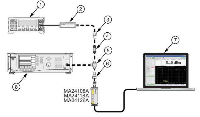
Index | Description |
1 | Reference Power Meter |
2 | Reference Power Sensor |
3 | K to N Adapter (if required) |
4 | 10 dB Attenuator |
5 | Power Splitter |
6 | K to N Adapter (if required) |
7 | PC with Anritsu PowerXpert Application |
8 | Synthesizer |
| |
Index | Description |
1 | Reference Power Meter |
2 | Reference Power Sensor |
3 | K to N Adapter (if required) |
4 | 10 dB Attenuator |
5 | Power Splitter |
6 | K to N Adapter (if required) |
7 | PC with Anritsu PowerXpert Application |
8 | Synthesizer |
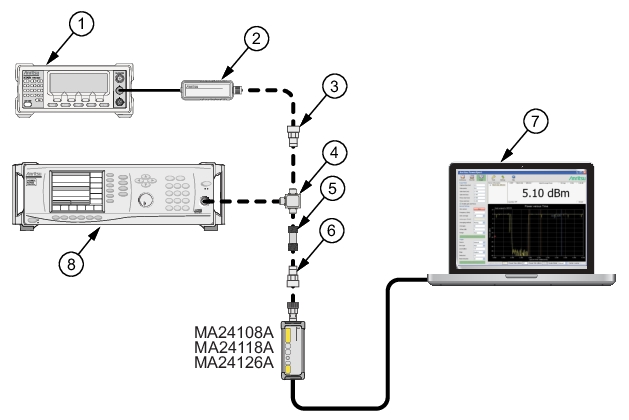 | |
Index | Description |
1 | Reference Power Meter |
2 | Reference Power Sensor |
3 | K to N Adapter (if required) |
4 | Power Splitter |
5 | 10 dB Attenuator |
6 | K to N Adapter (if required) |
7 | PC with Anritsu PowerXpert Application |
8 | Synthesizer |
Row # | Synthesizer Power Level Setting (dBm) | Attenuation in Reference Arm (dB) | A Reference Power Measurement (dBm) | B = (A6–A5) Correction (dB) | C = (A+B) Corrected Reference Power Measurement (dB) | Attenuation in Test Arm (dB) | D MA24108A, MA24118A, or MA24126A Measurement (dBm) | E = (C–D) Difference Calculation (dB) |
1 | +20 | 10 | 0 | |||||
2 | +15 | 10 | 0 | |||||
3 | +10 | 10 | 0 | |||||
4 | +5 | 10 | 0 | |||||
5 | 0 | 10 | 0 | |||||
6 | 0 | 0 | 10 | |||||
7 | +5 | 0 | 0 | 10 | ||||
8 | 0 | 0 | 0 | 10 | ||||
9 | –5 | 0 | 0 | 10 | ||||
10 | –10 | 0 | 0 | 10 | ||||
11 | Max: | |||||||
12 | Min: | |||||||
13 | Delta (E11 – E12): | |||||||
Note | The Correction column of rows 1 through 5 should all have the same value. The Correction column of rows 6 through 10 have values of 0. |
Row # | Synthesizer Power Level Setting (dBm) | Attenuation in Reference Arm (dB) | A Reference Power Measurement (dBm) | B = (A6–A5) Correction (dB) | C = (A+B) Corrected Reference Power Measurement (dB) | Attenuation in Test Arm (dB) | D MA24108A, MA24118A, or MA24126A Measurement (dBm) | C–D Difference Calculation (dB) |
1 | +20 | 10 | 0 | |||||
2 | +15 | 10 | 0 | |||||
3 | +10 | 10 | 0 | |||||
4 | +5 | 10 | 0 | |||||
5 | 0 | 10 | 0 | |||||
6 | 0 | 0 | 10 | |||||
7 | +5 | 0 | 0 | 10 | ||||
8 | 0 | 0 | 0 | 10 | ||||
9 | –5 | 0 | 0 | 10 | ||||
10 | –10 | 0 | 0 | 10 | ||||
11 | Max: | |||||||
12 | Min: | |||||||
13 | Delta (E11 – E12): | |||||||
Row # | Synthesizer Power Level Setting (dBm) | Attenuation in Reference Arm (dB) | A Reference Power Measurement (dBm) | B = (A6–A5) Correction (dB) | C = (A+B) Corrected Reference Power Measurement (dB) | Attenuation in Test Arm (dB) | D MA24108A, MA24118A, or MA24126A Measurement (dBm) | E = (C–D) Difference Calculation (dB) |
1 | +20 | 10 | 0 | |||||
2 | +15 | 10 | 0 | |||||
3 | +10 | 10 | 0 | |||||
4 | +5 | 10 | 0 | |||||
5 | 0 | 10 | 0 | |||||
6 | 0 | 0 | 10 | |||||
7 | +5 | 0 | 0 | 10 | ||||
8 | 0 | 0 | 0 | 10 | ||||
9 | –5 | 0 | 0 | 10 | ||||
10 | –10 | 0 | 0 | 10 | ||||
11 | Max: | |||||||
12 | Min: | |||||||
13 | Delta (E11 – E12): | |||||||
Row # | Synthesizer Power Level Setting (dBm) | Attenuation in Reference Arm (dB) | A Reference Power Measurement (dBm) | B = (A6–A5) Correction (dB) | C = (A+B) Corrected Reference Power Measurement (dB) | Attenuation in Test Arm (dB) | D MA24118A, MA24126A Measurement (dBm) | E = (C–D) Difference Calculation (dB) |
1 | +20 | 10 | 0 | |||||
2 | +15 | 10 | 0 | |||||
3 | +10 | 10 | 0 | |||||
4 | +5 | 10 | 0 | |||||
5 | 0 | 10 | 0 | |||||
6 | 0 | 0 | 10 | |||||
7 | +5 | 0 | 0 | 10 | ||||
8 | 0 | 0 | 0 | 10 | ||||
9 | –5 | 0 | 0 | 10 | ||||
10 | –10 | 0 | 0 | 10 | ||||
11 | Max: | |||||||
12 | Min: | |||||||
13 | Delta (E11 – E12): | |||||||
Row # | Synthesizer Power Level Setting (dBm) | Attenuation in Reference Arm (dB) | A Reference Power Measurement (dBm) | B = (A6–A5) Correction (dB) | C = (A+B) Corrected Reference Power Measurement (dB) | Attenuation in Test Arm (dB) | D MA24126A Measurement (dBm) | E = (C–D) Difference Calculation (dB) |
1 | +20 | 10 | 0 | |||||
2 | +15 | 10 | 0 | |||||
3 | +10 | 10 | 0 | |||||
4 | +5 | 10 | 0 | |||||
5 | 0 | 10 | 0 | |||||
6 | 0 | 0 | 10 | |||||
7 | +5 | 0 | 0 | 10 | ||||
8 | 0 | 0 | 0 | 10 | ||||
9 | –5 | 0 | 0 | 10 | ||||
10 | –10 | 0 | 0 | 10 | ||||
11 | Max: | |||||||
12 | Min: | |||||||
13 | Delta (E11 – E12): | |||||||