This procedure performs an AutoCal calibration using a full 2-port calibration with an internal thru, which is sufficiently accurate for most DUTs. The AutoCal Characterization file has already been loaded onto the VectorStar.
Required Equipment
• VectorStar MS4645B or MS4647B VNA with V (m) test port connectors, with Option 70—70 kHz Low End Frequency Extension.
• 36585V-2F Precision AutoCal Module, with V (f) connectors and required power and control cables. The AutoCal Characterization File has been loaded onto the VectorStar VNA.
• Test port cable, V (f) to V (m)
Procedure
1. Power up the VectorStar VNA.
2. Set the required Frequency Start, Frequency Stop, and Number of Points parameters.
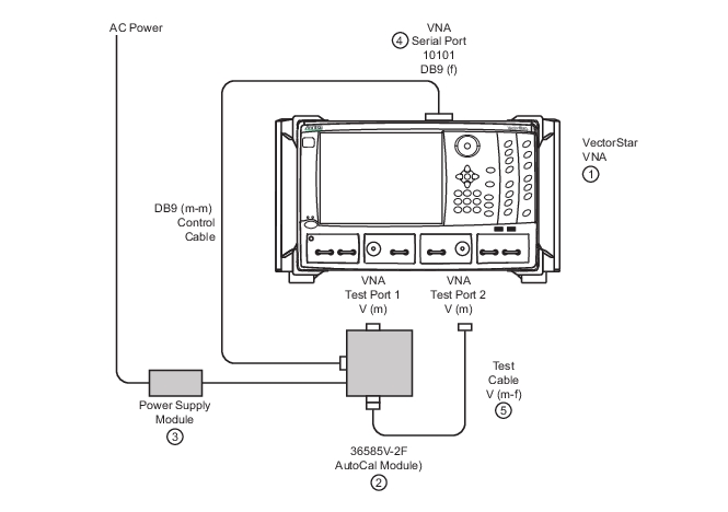
5. Connect the AutoCal V (f) connector directly to the VectorStar left side V (m) Test Port 1.
6. Connect the Serial Control Cable between the DB-9 connector on the top of the AutoCal Module and the Serial (10101) Port on the VectorStar rear panel.
7. Connect the coaxial power plug from the Power Supply Module to the AutoCal Module. Connect the other end to AC power.
8. Once connected to power, the AutoCal Module Power LED is illuminated green. When the module has warmed up to operating temperature, the LED illuminates as blue.
9. Connect the test cable between the V (m) Test Port 2 and the remaining AutoCal V(f) port.
Precision AutoCal 36585V-2F Cable Connections for Internal Through
1. MS4645B or MS4647B VNA with V Test Port Connectors
2. 36585V-2F AutoCal Module
3. AutoCal Power Supply Module
4. AutoCal DB9 (m-m) Control Cable connected between AutoCal Module and VNA rear panel Serial 10101 Port.
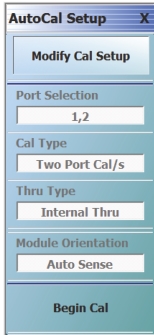
11. On the AUTOCAL SETUP (2-Port) menu, if the Port Selection, Cal Type, Thru Type, and Module Orientation display buttons do not show the correct values, click the Modify Cal Setup button.
• The MODIFY AUTOCAL SETUP dialog box appears. The exact name depends on the VNA mode and the user selections for the number of ports. The dialog box can be named:
• MODIFY 1-PORT AUTOCAL SETUP dialog box
• MODIFY 2-PORT AUTOCAL SETUP dialog box
• MODIFY 4-PORT AUTOCAL SETUP dialog box
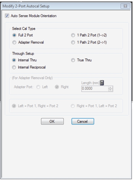
12. In this example, the required settings are for a Full 2-Port Calibration, with Auto Sense Module Orientation ON, and Internal Through while running on a VNA in 2-Port Mode. The resultant configuration dialog box is named MODIFY 2-PORT AUTOCAL SETUP, and is shown in Figure: MODIFY 2-PORT AUTOCAL SETUP Dialog Box.
MODIFY 2-PORT AUTOCAL SETUP Dialog Box
Settings for 2-Port AutoCal Calibration
• Auto Sense On
• Full 2-Port
• Internal Thru (Through)
13. On the MODIFY 2-PORT AUTOCAL SETUP dialog box, select the settings:
a. Cal Type Select area: Select the Full Two Port radio button.
b. Thru Select area: Select the Internal Thru radio button.
c. Auto Sense Module Orientation check box selected: Allows the AutoCal module determine left/right cable identification.
d. When the settings are complete, select OK to close the dialog box.
14. The AUTOCAL SETUP (2-Port) menu reappears with new values for Cal Type, Thru Type, and Module Orientation (see Figure: Configured AUTOCAL 2-Port Menu).
15. The window area at the bottom of the instrument display area appears with general instructions:
a. Ensure correct cable connections to AutoCal module.
b. Ensure that the Power and Operate LEDs are both illuminated.
c. Ensure characterization file is loaded before starting Cal. To load characterization file, go to the INSTALL (AUTOCAL CHARACTERIZATION) dialog box.
• MAIN | Calibration | CALIBRATION | Cal Kit/AutoCal Characterization | CAL KIT/AUTOCAL | Install Kit/Charc. | INSTALL (AUTOCAL CHARACTERIZATION)
d. Existing system setups such as averaging, power level, etc. will be applied during the cal.
Configured AUTOCAL 2-Port Menu
Settings for Port 1 and 2—Full Two Port—Internal Through—Auto Sense On
16. When ready, click the Begin Cal button.
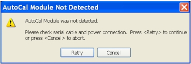
17. If the AutoCal module is connected incorrectly, the AUTOCAL MODULE NOT DETECTED warning message appears.
• Correct the connections as required and click Retry.
Note
A different dialog box may appear if the RF cables are connected incorrectly (with Autosense on) that states that Autosense was unable to determine the orientation of the module. If this dialog appears, and a large amount of loss is not present between the port and the AutoCal module, check the connections. If a known large amount of loss is present (from the test fixtures or the use of very long cables), the orientation should be manually entered.
18. When the calibration is complete, the Status Message dialog box will close and the display will return to the CALIBRATION menu with the Cal Status button set to ON. The assurance dialog will remain up with the pass/fail message, and must be manually closed.