Use this procedure to setup the minimum required instrument configuration parameters:
• Frequency Start
• Frequency Stop
• Number of Points
Any other required measurement parameters must be defined and applied before the AutoCal procedure. This section provides a highlight of typical additional measurement parameters.
Segmented Sweep
If required, segmented sweep must be setup in advance if the calibration needs a custom frequency list. See Frequency-Based Segmented Sweep.
IF Bandwidth (IFBW) and Averaging
IF Bandwidth and Averaging control the digital filtering and post-processing that determine the effective noise floor, the amount of trace noise, and, in some cases, the immunity to interfering signals. The trade-off for improved noise performance is slower sweep speed.
Port Power
Port power is less critical than IFBW or Averaging due to the excellent linearity of the VectorStar MS4640B Series VNA receivers. The AutoCal unit has an absolute maximum power limit of +10 dBm. The preferred calibration power is –10 dBm for improved accuracy at frequencies <100 MHz.
If power adjustments are required, any step attenuator settings must be selected before the calibration. Changes in the step attenuator settings alters both the RF match and the insertion loss in the measurements paths. Power can be changed after a calibration, but an attenuator change after a calibration invalidates the prior calibration.
Example Procedure
This example procedure assumes the VectorStar MS464xB Series VNA is equipped with the Option 70—70 kHz Low Frequency Extension and that only Frequency Start, Frequency Stop, Number of Points, and CW Mode settings are required.
1. Determine the values for the minimum setup parameters:
• Frequency Start: 70 kHz
• Frequency Stop: 70 GHz
• Number of Points: 200
• CW Mode: OFF
• Segmented Sweep: Not required
• IFBW: Defaults to 1 kHz
• Averaging: Defaults to no averaging
2. Power up the VectorStar and allow it to stabilize its internal temperature.
3. Navigate to the FREQUENCY menu:
• MAIN | Frequency | FREQUENCY
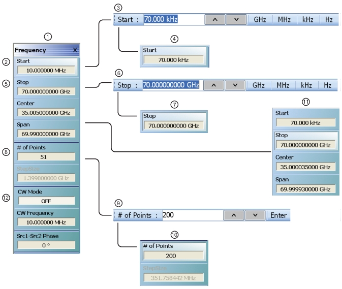
FREQUENCY Menu—Setting Initial AutoCal Parameters
1. FREQUENCY Menu
2. Start (Frequency) Button before.
3. Start Field Toolbar with 70.000 kHz set
4. Start Button after set to 70.000 kHz
5. Stop (Frequency) Button before
6. Stop Field Toolbar with 70 GHz set
7. Stop Button after set to 70 GHz
8. # (Number) of Points (Frequency) Button before
9. # of Points Field Toolbar with 200 points set
10. # of Points Button after set to 200 points. Below, Step Size automatically calculated to 351.758442 MHz.
11. Center (Frequency) Button automatically calculated to 35.00003500 GHz. Below, Span Button automatically calculated to 69.999930000 GHz.