This procedure performs an AutoCal procedure using a full 2-port calibration where a True Through (or external through) is required.
Required Equipment
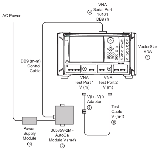
• VectorStar MS4645B or MS4647B VNAs with V(m) test port connectors, with Option 70, 70 kHz Low Frequency Extension.
• 36585V-2MF Precision AutoCal Module, with V(f) and V(m) connectors and required power and control cables. The AutoCal Characterization file has been loaded onto the VectorStar.
• Test port cable with V(f) to V(m) connectors
• Test port cable with V(f) to V(f) connectors, or a V(f) to V(f) adapter.
Procedure
1. Power up the VectorStar.
2. Set the required Frequency Start, Frequency Stop, and Number of Points parameters.
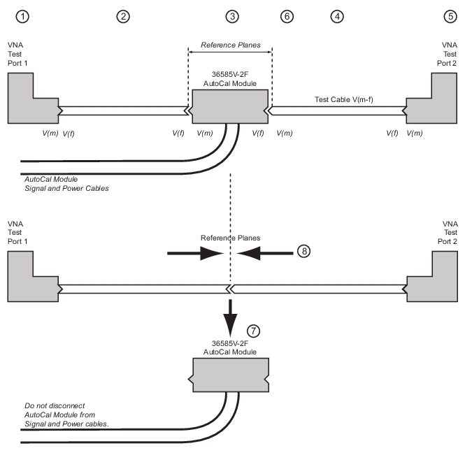
6. Resultant reference planes during first AutoCal procedure.
Part 2—AutoCal True Thru Procedure
7. After initial calibrations, user is directed to remove AutoCal module and connect test cables. At all times during the calibration procedure, the AutoCal module must be connected to the VNA and to AC power.
8. Connect the two Test Cables together to complete the through calibration.
7. On the AUTOCAL SETUP menu, if the Cal Type, Thru Type, and Module Orientation display buttons do not show the correct values, select the Modify Cal Setup button.
a. The MODIFY 2-PORT AUTOCAL SETUP dialog box appears.
b. Change the settings as required.
c. In the Cal Type Select area: Select the Full Two Port radio button.
d. In the Thru Select area, select the True Thru radio button and the THRU INFO dialog box appears.
e. Enter information about the through line. Enter 0 length and 0 dB/mm loss (and a reference frequency of 0, which forces it to use that loss at all frequencies) and 50 ohm impedance. Select OK to close the dialog box.
• Select the Auto Sense Module Orientation check box which allows the AutoCal module determine the left/right cable identification.
• Click OK to close the dialog box.
Note
All existing system setups such as IF Bandwidth, Averaging, and Power Level will be applied during the calibration procedure.
8. When ready, click the Begin Cal button.
9. A status dialog box with a progress bar appears after an AutoCal sequence has started. The status messages define has far the program has progressed and if any user actions are required.
10. At any time, the AutoCal sequence can be cancelled by clicking the dialog box Abort button.
11. A dialog box will appear when the true through is to be connected.
12. Connect the Test Port 1 test cable to the Test Port 2 test cable.
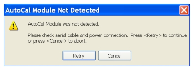
AUTOCAL MODULE NOT DETECTED Warning Message
If the AutoCal module is connected incorrectly, the AUTOCAL MODULE NOT DETECTED warning message appears. Correct connections as required and click the Retry button.
AutoCal True-Through Connections—Module Removed
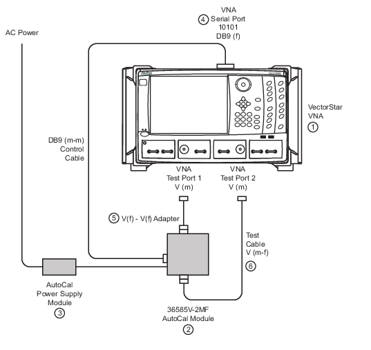
1. MS4645B or MS4647B VNA with V Test Port Connectors
2. 36585V-2MF AutoCal Module
3. AutoCal Module Power Supply connected to AC Power. AutoCal module and connect test cables. At all times during the calibration procedure, the AutoCal module must be connected to the VNA and to AC power.
4. AutoCal DB9 (m-m) Signal Cable connected to VNA Rear Panel Serial 10101 Port
5. V (f) to V (f) Adapter connected to Test Port 1 V (m)
6. V (m-f) Test Cable connected to V (f-f) adapter and Test Port 2 V (m)
13. After connecting the through, select Continue.
14. When the auto calibration is complete, a status message appears with a statement about assurance passing or failing. On the CALIBRATION menu, the Cal Status field button shows ON.
15. Closing the dialog box returns to the CALIBRATION menu.