While S-parameters (or the UN-ratioed wave parameters) are usually the display variables of interest, conversions to other parameters may be required and are possible with the VectorStar.
1/S is sometimes plotted, particularly for oscillators and other negative resistance devices, where it is desirable to fold the outside of the Smith chart back to the inside. Equivalent impedances and admittances are commonly needed for device modeling and the Z and Y conversions can be used for this (note that these are not, in general, Z and Y parameters).
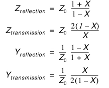
For each of these parameters, a conversion mode of reflection or transmission must be selected which indicates how the current parameter is to be interpreted. The calculations proceed as follows, where X indicates the current displayed parameter such as S11, S21, b1/a1, a2/a1, and user-defined parameters:
Equation 11‑3.
Note that reflection Z or Y values here represent shunt impedances or admittances while the transmission values represent series impedances or admittances.
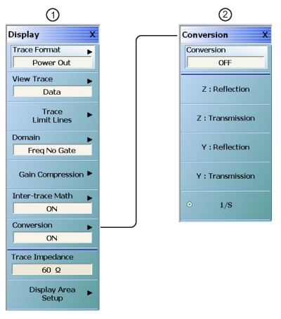
All of the choices available are on the CONVERSION menu shown in Figure: Conversion Control Menu. Note that this function is PER TRACE and is located in the DISPLAY menu.
Conversion Control Menu
1. DISPLAY menu (on left).
2. CONVERSION menu (on right).
The calculations are a function of the current reference impedance, which defaults to the calibration reference impedance unless impedance transform has been used (see the section above on Reference Plane Control) or the trace reference impedance has been changed.