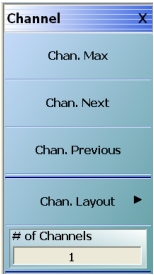
The channel menu itself is fairly simple. While the system defaults to 1 channel (under a preset command), here a different number of channels may be selected. The active channel (indicated by a thick white border) may be selected by clicking on that channel’s window or it can be incremented using this menu (Chan. Next and Chan. Previous). The button Chan. Max can be used to force the active channel to occupy the entire data screen area. Note that the other defined channels will continue to sweep even when this mode is entered. The Chan. Max command is a toggle and can be undone by clicking it again. Chan. Max can also be accomplished by double-clicking the channel area away from a specific graph (that leads to Trace Max discussed later). These commands are illustrated in the top level menu shown in Figure: CHANNEL Menu.
CHANNEL Menu
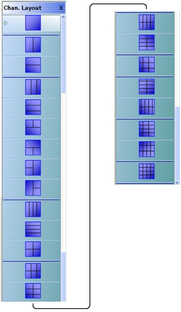
Once a given number of channels is selected, the layout of those channels is selected in a submenu shown in Figure: CHAN. LAYOUT (CHANNEL LAYOUT) Menu. Note that selecting a layout with more channels will update the channel count, since gaps in the sweep processing are not allowed. Because there are many combinations of channels possible, this window is quite lengthy (shown in two parts in Figure: CHAN. LAYOUT (CHANNEL LAYOUT) Menu).
CHAN. LAYOUT (CHANNEL LAYOUT) Menu
The instrument menu has a right-side scroll bar to access the entire menu.
Number of Channels
The number of channels available first depends on the VNA maximum point setting which in turn depends on the VNA model number.
• If the VNA is set to 100,000 point mode, only one channel is available, with up to 16 traces.
• If the VNA is set to 25,000 point mode, up to 16 channels can be defined, each with up to 16 traces.
If multiple channels are available in the VNA, any number of channels can be configured between 1 and 16 channels.
Only those values corresponding to semi-symmetric layouts are allowed, as suggested by the channel layout menu, and other entries will be coerced.
Once the number of channels and the layout has been selected, it then remains to define each of the channels. The sweep control parameters apply to the active channel so one may cycle through the channels, entering values as needed. Alternatively, the setups for a channel may be copied through the setup save/recall mechanism since setups can be saved on a per-channel basis. Note that save/recall can also be applied to all channels.
It has been discussed that most sweep-setup parameters are per-channel in nature. To clearly delineate when these apply, the per-channel functions include:
• Frequency
• Power (although step attenuator settings, for units with Option 61 or 62, are per-system)
• Option 61 Active Measurement Suite with Two (2) Attenuators, Option 62 Active Measurement Suite with Four (4) Attenuators Calibrations (RF, power, receiver, etc.); this includes the calibration reference impedance
• Embedding/de-embedding and reference plane extensions
• Multiple source control settings (to include broadband/mmWave)
• Impedance transformations (note that this is distinct from impedance parameter conversions which are a post-processing calculation on trace data)
• Post-processing order
• Media type (dielectric constants, coaxial vs. waveguide, etc.)
• Hold functionality (portions can be per-system)
• Trigger functionality (portions can be per-system or per port as well as per-channel)
• Analog out (rear panel)
Maximum Number of Points Setup
One additional behavior associated with channel count relates to the maximum number of points that may be defined in a sweep. Normally this limit is 25,000 pointsMS464xB Series VNAand this value can be used with any number of channels.
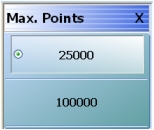
The VNA mode can be switched to a maximum of 100,000 points, but in this case, only one (1) channel is allowed. This mode is selected with the MAX. POINTS menu (shown below in Figure: MAX. POINTS (MAXIMUM POINTS) Menu) which is available at:
• MAIN | System | SYSTEM | Setup | SETUP | Max Points Setup | MAX. POINTS
This selection itself is, of course, per-system since the selection determines the number of channels that will be available.
MAX. POINTS (MAXIMUM POINTS) Menu
Example Three-Channel Setup
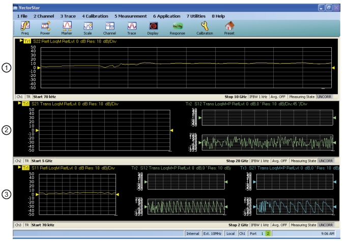
An example of a three-channel setup is shown in Figure: Typical Three-Channel Display. In this case, all three channels have different frequency ranges, the same IF bandwidth was used in each, and the first channel (at Figure: Typical Three-Channel Display—#1 on the top or Ch1) is active as indicated by the thick white border.
Typical Three-Channel Display
1. Channel 1 (Ch1 at top) is the active channel is active (note white border) and measuring S22.
2. Channel 2 (at middle) is measuring S21.
3. Channel 3 (at bottom) is measuring S11.
Hold Functions and Manual Trigger for Channels
Generally, the sweeps for each channel are executed sequentially. That is, all of the sweeps for Channel 1 are performed first, followed by all of those for Channel 2, and so on. Hold events and triggering events can be per-channel or per-system (and some subsets of the channel as well.) These menus are shown in Figure: HOLD FUNCTIONS Menu for hold events and Figure: MANUAL TRIGGER Menu for triggering events. The HOLD FUNCTIONS menu is available from the SWEEP SETUP menu.
Navigation:
• MAIN | Sweep Setup | SWEEP SETUP | Hold Functions | HOLD FUNCTIONS
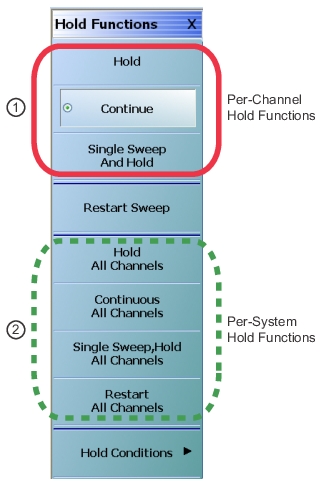
Note that while triggering can be done per-point and per-port, it still refers to the setup of the channel and it is never reduced to measurements related to a trace. As these hold and trigger functions are used, the actual measurement sequence can, of course, change. The HOLD FUNCTIONS menu is shown below to illustrate some per-system aspects (green dashed circle) of the hold function as opposed to the usual per-channel functions at the top of the menu (red circle).
HOLD FUNCTIONS Menu
1. Per-channel hold functions (at top).
2. Per-system hold functions (at bottom).
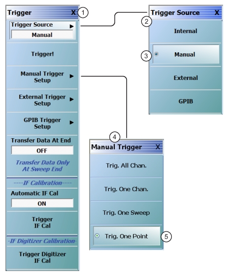
Trigger Source—Manual Trigger Menu
The Manual Trigger menu is shown below to illustrate per-channel behavior (second button), per-portion-of-channel behavior (third and fourth buttons), and per-system behavior (first button). Other trigger modes have analogous behaviors.