The third type of pulse measurement is pulse-to-pulse, where transient effects from the beginning of DUT excitation may be of interest. Thermal phenomena are often studied with this method.
From a measurement point-of-view, pulse-to-pulse is something of a hybrid of point-in-pulse and pulse profiling techniques. In point-in-pulse, a single window per period (relative to T0) is being measured. In the pulse profiling, data is being collected and plotted versus time with frequency and power held constant. By definition, during pulse-to-pulse measurements, averaging between pulses is not permitted.
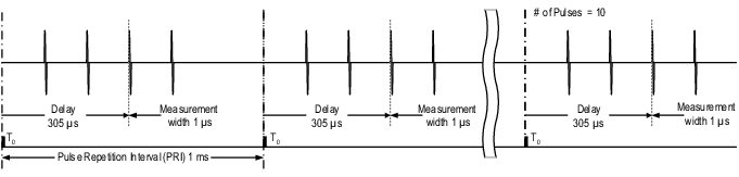
An absolute time reference is often needed in pulse-to-pulse measurement applications. Consequentially, some external or manual triggering is used to begin the sequence of events. In this example, the manual trigger on the VNA will be used. When the trigger is executed, the pulse generator outputs will activate and, in this case, begin applying bias and RF to the device. The purpose of the measurement is to capture the evolution of S21 of the DUT over the first 10 pulses. The PRI is 1 ms, and quadruplet pulsing on both bias (3 supplies for this DUT) and RF is desired.
The relative delays are 100 μs between each leading edge of the quadruplet, and the width of each sub-pulse is 10 μs. The desired measurement window is 1 μs centered within the last pulse of the quadruplet.
Setup
• PRI: 1ms
• Pulse generators 1 to 4: quadruplet with delays of 0, 100 μs, 200 μs, and 300 μs, and all widths at 10 μs
• Measurement delay: 305 μs
• Measurement width: 1 μs
• IFBW: 1 MHz
• Frequency: 25 GHz
The processing window will apply to a1, b1, and b2 in this example (off-state behavior is not of interest). The timing relationship for this measurement is shown in Figure: Pulse Profiling Example Results.
Timing Relationship for the Pulse-to-pulse Measurement Example
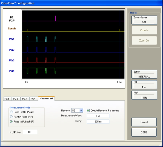
Pulse-to-pulse Example Setup Dialog
The Pulse Configuration dialog box is shown in Figure: Pulse-to-pulse Example Setup Dialog. Here, the receivers are selected to have coupled parameters, and the measurement (for all channels) is roughly centered within the final pulse of the quadruplet. The three external bias systems required positive polarity, while the RF stimulus requires inverted polarity.
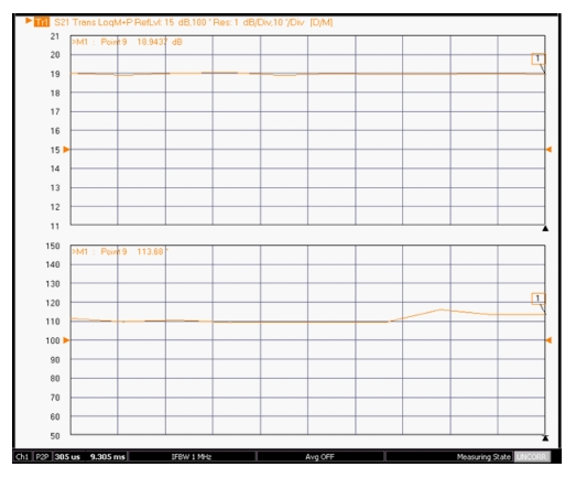
Measurement Results for the Pulse-to-pulse Measurement Example
Trace normalization was used for this measurement.
Pulse-to-Pulse Measurement Results
There are many ways to trigger this kind of measurement, and there are many potential variations depending on the hardware and measurement behaviors of interest. To help determine the measurement configuration, answering the following questions may be of help:
• What needs to be activated when the sequence begins? Some or all of the pulse drives? Some or all static drives (RF, bias, or control)?
• If the trigger is being generated externally, are there latencies involved and are they consistent? If being routed from the internal VNA trigger (via the pulse generators), do any external paths involved have latencies?
• Is it known how long the DUT must be 'cold' (time prior to the trigger event) to be in a steady state for whatever mechanism is of interest? If multiple mechanisms are of interest, is there a way of organizing the timing to isolate the mechanism of interest (sequencing biasing, for example)?