In the AutoCal-specialized version, adapter removal primarily refers to the case of a gender incompatibility when it is not desired to use test port converters (for example, an M-F AutoCal unit used to establish M-M reference planes). A separate menu item shown below (see Figure: AutoCal Setup Dialog with Adapter Removal Selected) is provided for AutoCal adapter removal to speed up the process since fewer manual steps are needed. In this calibration sequence, an adapter that can mate the desired reference plane connectors is used as a part of the calibration.
There are two possible ways to accomplish this, both using a pair of calibration sequences to remove the effects of the adapter. In both of the cases below, it is assumed all connectors are from the same family. If not, as with a special inter-series AutoCal unit, this AutoCal-specific adapter removal technique cannot be used. Instead, see the standard adapter removal section.
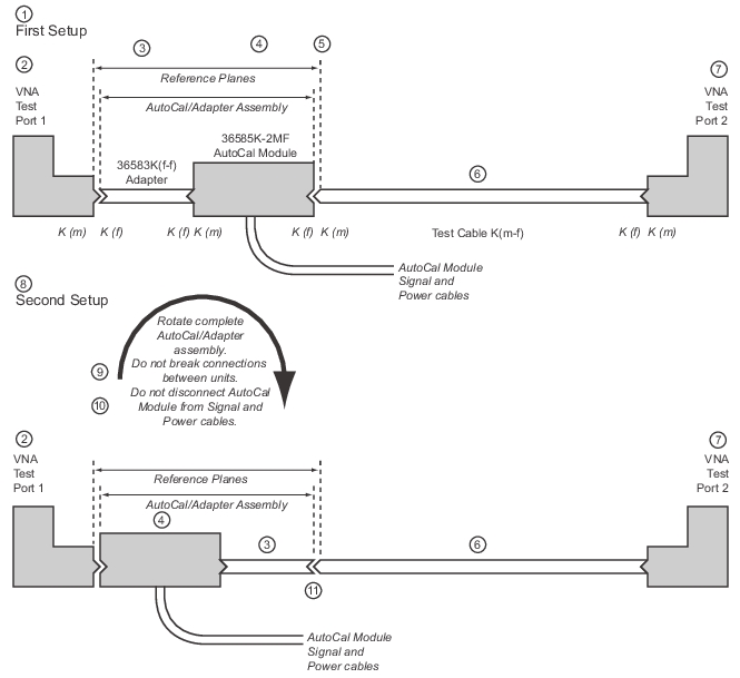
AutoCal M-F Module, M-M Reference Planes, and Adapter Removal Calibration (1 of 2)
Part 1—AutoCal Adapter Removal Procedure
1. First setup for the Adapter Removal procedure.
2. VNA Test Port 1
3. 36583K (f-f) Adapter
4. 36585K-2MF AutoCal Module—For the duration of the calibration, the K (f-f) Adapter and the AutoCal Module must be connected as an assembly. Do not disassemble or disconnect from its Power and Signal cables.
5. Resultant calibration reference planes.
6. K (m-f) Test Cable
7. VNA Test Port 2
Part 2—AutoCal Adapter Removal Procedure
8. Second setup for the Adapter Removal procedure.
9. After the first calibration, rotate the complete assembly so that the AutoCal K (f) connector is connected to VNA Test Port 1. Do not disconnect the Adapter from the AutoCal module.
10. Do not disconnect the AutoCal Module from its Power or Signal cables.
11. Connect the 36583 K (f-f) adapter to the Test Cable K (m-f). The reference planes remain in place. The user is guided through the remaining steps of the procedure.
1. Place the adapter on the port of the AutoCal unit. The instrument will ask which port the adapter is on
2. Connect the AutoCal unit and the system will perform the first auto calibration
3. Flip the AutoCal and adapter assembly around so that the VNA port connections have changed (do not remove the adapter from the AutoCal assembly).
4. The system will perform a second auto calibration.
M-M or F-F AutoCal Unit With MF Reference Planes
1. Place an adapter on the port of the AutoCal unit. The instrument will ask which port the adapter is on.
2. Connect the AutoCal unit and the system will perform the first auto calibration.
3. Direct-connect the desired MF reference plane (which is, of course possible, by definition here).
4. The system will perform some additional measurements on this thru connection and complete the calibration.
Note
For the 36581x and 36582x AutoCal modules, which only come in M-F versions, only the first type of AutoCal adapter removal will be available.
AutoCal Setup Dialog with Adapter Removal Selected
MODIFY 2-PORT AUTOCAL SETUP Dialog Box—Auto Sense ON—Adapter Removal—Internal Thru