At their root, the measurements discussed in this chapter are still S‑parameter (or perhaps unratioed parameter) measurements. Even though they are conducted in a pulsed environment, for the most part, nothing has changed in terms of availability or execution of calibrations. There are, however, some subtleties to keep in mind.
Power Calibrations
There are a number of different ways that power can be calibrated:
• Unpulsed using a normal CW power sensor. This is the simplest method, and ensures accuracy of the average or midpoint on-state power. This is preferably done with the pulse modulator in place, but biased on so that the insertion loss of the modulator is included. The Anritsu pulsed test sets allow this to be done without external pulsing by using the invert switch on the rear panel.
• Pulsed using a normal CW power sensor. This will calibrate the power to the average pulsed power. For most power meters, a duty cycle can be entered that will correct this value to an average on-state power (and the VNA will not preset the power meter, so this duty cycle can be entered manually on the power meter; the VNA will not do this)
• Pulsed using a pulse power sensor (the Anritsu MA2411B sensor (used with the ML249X meter) and the Rhode & Schwarz NRP-Z85 sensor (used with the NRP2 meter) are supported at this time). This is the most flexible approach, since power can be calibrated to a particular portion of the pulse, so it allows, for example, calibrating to peak power with significant resolution control.
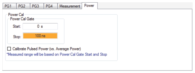
• In the PulseView configuration dialog, a tab is available where the gate start and stop are defined. It is only the power in this time range (relative to the PRI start) that will be used for calibration. The dialog to support pulse power sensor-based user power calibrations is shown in Figure: Pulse Power Sensor-based User Power Calibrations Dialog Box. The time interval over which power data should be used (relative to the period start) is entered and a check box (replicated on the power calibration menu) enables its use.
Pulse Power Sensor-based User Power Calibrations Dialog Box
• If the Calibrate Pulsed Power (vs. Average Power) box in this dialog (also available from the Power Calibration dialog) is checked, the pulsed power meter will be directed to enter profiling mode and to measure just in the gated region. An error will occur at the power calibration stage if a pulsed power meter is not available. If unchecked, average power (over the whole cycle) will be calibrated.
• Note that the pulsed power meter must be synchronized to the beginning of the PRI and this is usually done by connecting Synch Out from the VNA to the external trigger input of the power meter. If an external pulse generator is part of the setup, it can also sometimes be used as the sync source for the power meter as long as the time alignment makes sense.
• The gate start and stop range cannot exceed 2*PRI.
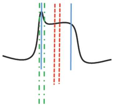
• The gate placement can be adjusted depending on the desired leveling target; some examples are shown in Figure: Some Possible Gate Orientations That Might be Used for Pulsed Power Calibrations. The entire on-state of the pulse could be averaged to create the power measurement (solid gate markers below), the midpoint of the pulse could be used (dashed gate markers below), the initial overshoot could be used (dot-dash gate markers below), etc. The gate selection relative to the pulse shape will be visible on the pulsed power meter screen to help with confirmation of the choice. An example is shown in Figure: Screen Shot of ML249X Power Meter After a Pulsed Power Calibration on the VNA.
Some Possible Gate Orientations That Might be Used for Pulsed Power Calibrations
The solid gates would ensure that the average on-state pulsed power would be close to the target value. The dashed gate would force the mid-pulse-power to be close to target. The dot-dash gate would instead make the peak intra-pulse power be close to the target value.
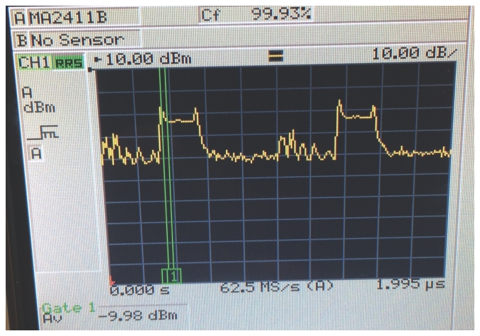
Screen Shot of ML249X Power Meter After a Pulsed Power Calibration on the VNA
The gate (marked by green lines) was selected to be near the rising edge and the power calibration was targeted at -10 dBm in that zone.
• Resolution limits must be observed (2.5ns increment) even if the power meter may use many cycles to improve resolution. Note that available gating resolution will be reduced at lower carrier frequencies just as happens with measurement resolution.
Receiver Calibrations
These are done in pulse mode and can be done with stimulus pulsing disabled (typical) or enabled. If stimulus pulsing is used, it is important to ensure the measurement window placement does not occur during an off-period in that given path.
User RF Calibrations
(For example, S-parameter calibrations such as SOLT, LRL, etc.)
User RF calibrations are done while in pulsed mode. If stimulus pulsing will be used in the measurement, it should be used in calibration as well. This will allow for correction of any minor pulse distortions that may occur in the stimulus system. If using an Anritsu pulse modulator test set, extra reference couplers are provided so that a pulsed reference can be provided to the system. Applying this reference can help reduce trace noise and minimize any video contamination that may occur in a measurement. If the stimulus is not being pulsed (for example, only DUT or bias pulsing is being used), utilization of these additional reference signals is not needed.
Note
If the reference couplers in an Anritsu pulsed test set are used, the ALC detection system will still detect the un-pulsed signal, but the extra loop port should be terminated to avoid minor power inaccuracies. The ALC detection circuitry is in the reference path of the VNA, but prior to the reference access loop where the pulsed version is injected. Reference couplers are discussed in Minimizing Uncertainties.
All standard S‑parameter calibration methods apply, the selection of which continues to be governed by the media and standards available—as discussed in other chapters of this guide.
Although not nearly as influenced by changes in pulse parameters as the narrowband or triggered measurement methods, the high-speed digitizer pulse measurement method still has some calibration dependence on the pulse parameters. If those parameters change, a new calibration may be needed, depending on the uncertainty tolerance.
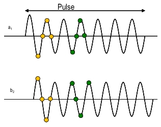
To understand the effect of changing pulse measurement parameters, consider the IF waveforms shown in Figure: Example of Pulse Parameter Change Affecting Calibration. They illustrate a simple 2-port transmission calibration step, where a thru line is connected and stimulus pulsing is being used.
For example, take overshoot on the stimulus pulse. If the measurement window is toward the leading edge of the pulse (yellow samples), some of the overshoot may be included in the measurement. In some cases (a long thru line, for example), the overshoot may not be entirely symmetric (occurring at the same time) between measurement channels (a1 and b2, for example).
If the measurement window is moved later (green samples), then there is no overshoot present and the b2/a1 ratio has changed. Depending on the pulse and window positions, this could cause a fractional dB error in measurement unless recalibrated. Since there is partial ratioing, the maximum error is always less than the maximum overshoot, but could be in the 10 % to 30 % of peak overshoot in a worst-case scenario.
Example of Pulse Parameter Change Affecting Calibration
The decision whether to recalibrate can be affected by a number of parameters. These guidelines may help to determine whether to recalibrate the instrument:
• No stimulus pulsing is used (for example, using only bias or DUT control pulsing): With this configuration, calibrations are largely invariant to pulse parameters, and recalibration is normally not required. An exception may occur when performing an externally-triggered pulse measurement and the measurement window is close to the trigger event. In that case, experimentation with recalibration may be required to determine if there are any material effects from the measurement setup.
• Stimulus pulsing is used: As in the example of Figure: Example of Pulse Parameter Change Affecting Calibration, it may be desirable to recalibrate if it is believed that the measurements occur at a point for which there is some overshoot from the stimulus. If the test is made using an Anritsu pulse modulator test set, this overshoot is less than ~0.5 dB and only covers about the first 5 ns. If not using that time zone, or if that zone is used but ~0.1 dB impact is not significant, then one need not recalibrate. If using another stimulus modulator, one should consider its response pattern.
• Receive-side modulation is used (receiver-gating as shown in Figure: Receiver Gating Using the Receiver-side Modulators): If one needs to operate near the edge of the modulator pulse, and if one is sensitive to small errors, then recalibration is recommended.
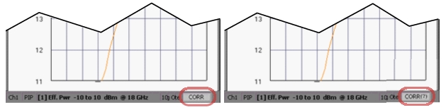
If pulse parameters are changed after calibration, the CORR annunciator on screen (which indicates that a calibration is applied) may change to CORR(?) to indicate the possibility that the calibration has been disturbed. See Figure: On Screen Calibration Disturbance Indication—CORR versus CORR(?). The measurements may still be entirely valid based on the exact pulse measurement configuration (see the recalibration guidelines above).
On Screen Calibration Disturbance Indication—CORR versus CORR(?)