 | |
Index | Description |
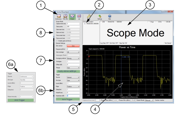
1 | Toolbar - See Toolbar. |
2 | Sensor Information Area showing sensor model and serial number, communications port, and firmware version. |
3 | The measurement ans status window is described in Measurement and Status Window (Note that the screen shown for MA24105A displays two values, forward and reverse). |
4 | Graphical Display for each mode |
5 | Graphical Settings for each mode: |
6 | Trigger Settings is available with the MA24x08A, MA24x18A, MA24126A and MA243x0A only. See Trigger Settings. The Arm Trigger button must be clcked to apply any setting changes. 6a – MA241xxA models only–Trigger setting includes “Noise Immunity”. 6b – MA242x8A and MA243x0A models only–Trigger setting includes “Hysteresis” around the trigger level and “Holdoff”. |
7 | The Apply above settings button must be clicked to apply any setting changes. See General Settings. |
8 | The settings for the selected mode type (Continuous, Time Slot, Scope, or List mode) is displayed. The Apply above settings button must be clicked to apply any setting changes. |